Garmin AT
Rev --
7-32
GX Service Manual
© 2004 Garmin AT
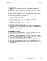
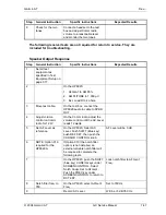
1. Transmitter Tests Using the HP8920 Test Set
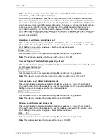
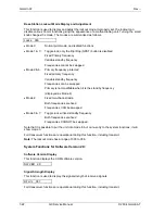
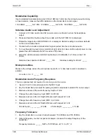
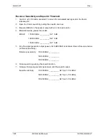
This test will require MON and Test Mode adjustments. Record MON and Test mode settings
before proceeding. See the Service Data Sheet located in chapter 21 of this manual.
Flip/Flop Input (Not present on GX50/55)
Description:
The frequency flip/flop input is a discrete input intended for connection to a
momentary button to aircraft ground.
Setup:
Connect the unit to nominal input supply. Connect a momentary switch from the
flip/flop input to ground.
Operation:
After powering the unit on, press the COM smart key to see the frequencies.
Ensure that the active and standby frequencies are not the same. Push the
flip/flop momentary switch several times.
Verification:
Verify the frequencies flip/flop when pressing the momentary switch.
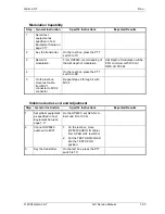
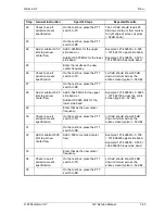
TX Power
Step
General Instruction
Specific Instructions
Expected Results
1 Set
all
test
equipment as
specified in Test
Equipment Setup on
page 7-17.
No Modulation.
2
Key transmitter.
On the test box press, the PTT
switch to TX.
3
Record power.
Record TX Power from HP8920.
TX PWR >8 watts with no
transmitter audio at 25°C + 4°.
TX PWR >7 w at –20°C and at
+55 °C.
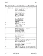
Optional:
repeat this
test with DC input voltage
between 10 VDC and 40 VDC.
The battery protection circuit is
on below 13.75 V.
At 10 VDC input the transmitter
power should be 6 watts. At 9
VDC the PTT should lock out.
4
On the test box, press the PTT
switch to RX.
5
Repeat this test at frequencies
118.0 MHz and 136.975 MHz.
Summary of Contents for APOLLO GX SERIES
Page 8: ...Garmin AT Rev viii GX Service Manual 2004 Garmin AT This Page Intentionally Left Blank...
Page 12: ...Garmin AT Rev 1 4 GX Service Manual 2004 Garmin AT...
Page 24: ...Garmin AT Rev 2 12 GX Service Manual 2004 Garmin AT...
Page 26: ...Garmin AT Rev 3 2 GX Service Manual 2004 Garmin AT...
Page 27: ...2004 Garmin AT GX Service Manual 4 1 Chapter 4 Antenna Installation Guides...
Page 28: ...Garmin AT Rev 4 2 GX Service Manual 2004 Garmin AT...
Page 32: ...Garmin AT Rev 5 4 GX Service Manual 2004 Garmin AT...
Page 96: ...Garmin AT Rev 7 58 GX Service Manual 2004 Garmin AT...
Page 98: ...Garmin AT Rev 8 2 GX Service Manual 2004 Garmin AT Figure 8 1 GX55 Assembly Board Locations...
Page 122: ...Garmin AT Rev 8 26 GX Service Manual 2004 Garmin AT...
Page 130: ...Garmin AT Rev 9 8 GX Service Manual 2004 Garmin AT...
Page 140: ...Garmin AT Rev 10 10 GX Service Manual 2004 Garmin AT Figure 10 5 Comm Board Block Diagram...
Page 152: ...Garmin AT Rev 10 22 GX Service Manual 2004 Garmin AT...
Page 158: ...Garmin AT Rev 11 6 GX Service Manual 2004 Garmin AT...
Page 160: ...Garmin AT Rev 12 2 GX Service Manual 2004 Garmin AT...
Page 162: ...Garmin AT Rev 13 2 GX Service Manual 2004 Garmin AT...
Page 165: ......
Page 166: ......


