


Garmin AT
Rev --
7-42
GX Service Manual
© 2004 Garmin AT
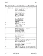
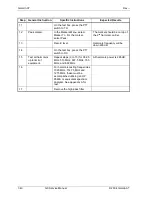
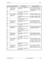
Step
General Instruction
Specific Steps
Expected Results
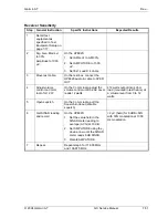
9
Set to Marker Menu. Turn the CURSOR CONTROL
knob to Main in the Controls
Field. Push the CURSOR
CONTROL knob. Turn the
CURSOR CONTROL knob CW
to Marker. Push the CURSOR
CONTROL knob. Turn the
CURSOR CONTROL knob CW
to Peak on the first Marker To
menu.
10
Turn on the
transmitter.
On the test box, press the PTT
switch to TX.
The RF modulation mask
should display on the screen.
11
Marker to peak of
carrier.
Press CURSOR CONTROL
knob.
Puts the marker on top of the
carrier.
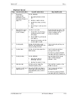
12
Marker to Center
Freq.
Turn the CURSOR CONTROL
knob to Center Freq. in the
second Marker To menu.
13
Carrier to center of
screen.
Press CURSOR CONTROL
knob.
This center carrier on the
screen.
14
Turn CURSOR CONTROL knob
to Lvl field on the right side of
the display.
15
Set carrier reference
level.
Press SHIFT REF SET. Press
CURSOR CONTROL knob.
This sets the amplitude
reference to the peak of the
carrier.
16
Turn CURSOR CONTROL knob
back to Marker. Push CURSOR
CONTROL knob.
17
Select Main with the CURSOR
CONTROL knob. Push to select.
18
Move CURSOR CONTROL knob
to Center Freq.
19
Get exact center
freq.
Record center freq.
Example 127.499639 MHz.
20
Add or subtract 12.5
kHz to get new
center freq.
Add 0.0125 MHz for the upper
side band, or
Subtract 0.0125 MHz for the
lower side band.
Example: 127.499639 MHz +
0.0125 = 127.upper
side band.
Example: 127.499639 MHz -
0.0125 = 127.499639 lower
side band.
21 Set
Spectrum
Analyzer to new
center frequency.
Enter the result as the center
frequency using the keypad.
Push CURSOR CONTROL knob
to enter new Center Freq.
Summary of Contents for APOLLO GX SERIES
Page 8: ...Garmin AT Rev viii GX Service Manual 2004 Garmin AT This Page Intentionally Left Blank...
Page 12: ...Garmin AT Rev 1 4 GX Service Manual 2004 Garmin AT...
Page 24: ...Garmin AT Rev 2 12 GX Service Manual 2004 Garmin AT...
Page 26: ...Garmin AT Rev 3 2 GX Service Manual 2004 Garmin AT...
Page 27: ...2004 Garmin AT GX Service Manual 4 1 Chapter 4 Antenna Installation Guides...
Page 28: ...Garmin AT Rev 4 2 GX Service Manual 2004 Garmin AT...
Page 32: ...Garmin AT Rev 5 4 GX Service Manual 2004 Garmin AT...
Page 96: ...Garmin AT Rev 7 58 GX Service Manual 2004 Garmin AT...
Page 98: ...Garmin AT Rev 8 2 GX Service Manual 2004 Garmin AT Figure 8 1 GX55 Assembly Board Locations...
Page 122: ...Garmin AT Rev 8 26 GX Service Manual 2004 Garmin AT...
Page 130: ...Garmin AT Rev 9 8 GX Service Manual 2004 Garmin AT...
Page 140: ...Garmin AT Rev 10 10 GX Service Manual 2004 Garmin AT Figure 10 5 Comm Board Block Diagram...
Page 152: ...Garmin AT Rev 10 22 GX Service Manual 2004 Garmin AT...
Page 158: ...Garmin AT Rev 11 6 GX Service Manual 2004 Garmin AT...
Page 160: ...Garmin AT Rev 12 2 GX Service Manual 2004 Garmin AT...
Page 162: ...Garmin AT Rev 13 2 GX Service Manual 2004 Garmin AT...
Page 165: ......
Page 166: ......