


Garmin AT
Rev --
8-12
GX Service Manual
© 2004 Garmin AT
Display Replacement
This procedure describes the removal and replacement of the display board and the display controller
board.
Parts Required
•
145-2341-00 ELECTROLUMINESCENT DISPLAY, PLANAR, 80 x 160 PIXEL
•
221-0212 SCREW, PAN HEAD PHILIPS, 2-56 X 3/16", STAINLESS STEEL, SEMS, INT (5
required)
•
252-0209 MF, 3/16", HEX, 2-56 x ¼", STAINLESS STEEL (4 required)
•
418-5107-00 FLEX CIRCUIT ASSEMBLY, SOFT KEY
•
664-0042
LOCTITE,
242
Removal
1. Before starting this procedure, fill out a Service Data Sheet if this has not already been done. A
copy is located at the back of this manual.
2. Power the unit off and disconnect power from the unit.
3. Remove the bezel assembly (see Bezel Assembly Replacement procedure).
4. Unplug the flex cable from the zif socket on the back of the display controller board by gently
unsnapping the collar on the zif socket and removing the flex cable.
5. Remove the three knobs from the rotary switch shafts using the 0.050" hex driver.
6. Remove the five screws holding the display controller board to the bezel.
7. Carefully lift the display controller board off the display board unplugging the connector under the
display controller board.
8. Remove the four standoffs holding the display board to the bezel.
9. Remove the display board from the bezel.
Replacement
Note:
When installing a new display board or display controller board, the display board and the
display controller board are to be kept together as a matched pair. They must be replaced
together.
1. The display board and display controller board come fastened together by a plastic standoff.
Carefully remove the plastic standoff and discard.
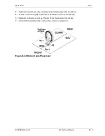
2. Peel the paper backing off the Soft Key Flex Circuit Assembly. Put the new Soft Key Flex Circuit
Assembly on the new display according to Figure 8-5. With the display facing you, the Flex Circuit
assembly is pressed into place and held by adhesive backing with flex cable to the right.
Warning
High voltage up to 200 VDC is present on the display board. Use extreme caution when
performing maintenance procedures with the cover removed.
Summary of Contents for APOLLO GX SERIES
Page 8: ...Garmin AT Rev viii GX Service Manual 2004 Garmin AT This Page Intentionally Left Blank...
Page 12: ...Garmin AT Rev 1 4 GX Service Manual 2004 Garmin AT...
Page 24: ...Garmin AT Rev 2 12 GX Service Manual 2004 Garmin AT...
Page 26: ...Garmin AT Rev 3 2 GX Service Manual 2004 Garmin AT...
Page 27: ...2004 Garmin AT GX Service Manual 4 1 Chapter 4 Antenna Installation Guides...
Page 28: ...Garmin AT Rev 4 2 GX Service Manual 2004 Garmin AT...
Page 32: ...Garmin AT Rev 5 4 GX Service Manual 2004 Garmin AT...
Page 96: ...Garmin AT Rev 7 58 GX Service Manual 2004 Garmin AT...
Page 98: ...Garmin AT Rev 8 2 GX Service Manual 2004 Garmin AT Figure 8 1 GX55 Assembly Board Locations...
Page 122: ...Garmin AT Rev 8 26 GX Service Manual 2004 Garmin AT...
Page 130: ...Garmin AT Rev 9 8 GX Service Manual 2004 Garmin AT...
Page 140: ...Garmin AT Rev 10 10 GX Service Manual 2004 Garmin AT Figure 10 5 Comm Board Block Diagram...
Page 152: ...Garmin AT Rev 10 22 GX Service Manual 2004 Garmin AT...
Page 158: ...Garmin AT Rev 11 6 GX Service Manual 2004 Garmin AT...
Page 160: ...Garmin AT Rev 12 2 GX Service Manual 2004 Garmin AT...
Page 162: ...Garmin AT Rev 13 2 GX Service Manual 2004 Garmin AT...
Page 165: ......
Page 166: ......