Garmin AT
Rev --
© 2004 Garmin AT
GX Service Manual
7-27
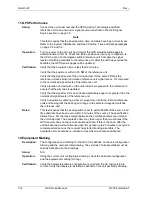
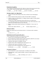
Spurious Emission without Modulation
This is an optional test not required for returning a unit to service.
1. Key the transmitter on a clear channel near 127.5 MHz.
2. Observe the carrier output with a spectrum analyzer and record for reference.
3. Measure power level at 2
nd
harmonic (255 MHz).
4. Measure the power level of the 3
rd
harmonic (382 MHz).
5. Measure the power level of all harmonics up to the 10
th
harmonic.
Note:
If the dynamic range of the spectrum analyzer is not great enough, insert a high pass filter
(188 MHz) between the transmitter and spectrum analyzer. Be sure to calibrate out the high pass
filter’s insertion loss.
Harmonic energy: ______ down at least 65 dBc
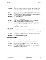
3. Receiver Tests
Headset Output Level
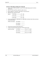
1. Inject a 1000 µV RF signal with 85% AM modulation into the Comm antenna port.
2. Channel the Comm to the same frequency as the signal generator.
3. Connect a 100 ohm resistor and AC power meter (or voltmeter) across the headphone
output.
4. Turn up the volume control on the Comm radio to make sure the output power can be greater
than 280 milliwatts (5.92 Vrms across 100 ohms).
Headphone drive capable of 280 mW: _____ OK
Speaker Audio Level
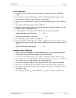
1. Inject a 1000 µV RF signal with 85% AM modulation into the Comm antenna port.
2. Channel the Comm to the same frequency as the signal generator.
3. Connect a 4 ohm resistor and AC power meter (or voltmeter) across the speaker output.
4. Turn up the volume control on the Comm radio to make sure the output power can be greater
than 12 watts (6.93 Vrms volts across 4 ohms).
Speaker drive capable of 12 Watts: _____ OK
Summary of Contents for APOLLO GX SERIES
Page 8: ...Garmin AT Rev viii GX Service Manual 2004 Garmin AT This Page Intentionally Left Blank...
Page 12: ...Garmin AT Rev 1 4 GX Service Manual 2004 Garmin AT...
Page 24: ...Garmin AT Rev 2 12 GX Service Manual 2004 Garmin AT...
Page 26: ...Garmin AT Rev 3 2 GX Service Manual 2004 Garmin AT...
Page 27: ...2004 Garmin AT GX Service Manual 4 1 Chapter 4 Antenna Installation Guides...
Page 28: ...Garmin AT Rev 4 2 GX Service Manual 2004 Garmin AT...
Page 32: ...Garmin AT Rev 5 4 GX Service Manual 2004 Garmin AT...
Page 96: ...Garmin AT Rev 7 58 GX Service Manual 2004 Garmin AT...
Page 98: ...Garmin AT Rev 8 2 GX Service Manual 2004 Garmin AT Figure 8 1 GX55 Assembly Board Locations...
Page 122: ...Garmin AT Rev 8 26 GX Service Manual 2004 Garmin AT...
Page 130: ...Garmin AT Rev 9 8 GX Service Manual 2004 Garmin AT...
Page 140: ...Garmin AT Rev 10 10 GX Service Manual 2004 Garmin AT Figure 10 5 Comm Board Block Diagram...
Page 152: ...Garmin AT Rev 10 22 GX Service Manual 2004 Garmin AT...
Page 158: ...Garmin AT Rev 11 6 GX Service Manual 2004 Garmin AT...
Page 160: ...Garmin AT Rev 12 2 GX Service Manual 2004 Garmin AT...
Page 162: ...Garmin AT Rev 13 2 GX Service Manual 2004 Garmin AT...
Page 165: ......
Page 166: ......

