


Garmin AT
Rev --
© 2004 Garmin AT
GX Service Manual
8-13
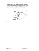
3. Place the display board in the bezel assembly with the flex cable at the bottom next to the data
card slot. Ensure that the five smart key buttons and keypad are in place. Fasten the display
board in place using four standoffs (252-0209).
Torque the standoffs to 4.2 lb.-in.
Caution: Do not exceed 4.2 lb.-in of torque.
4. Carefully plug the display controller board into the connector below on the display board. Ensure
that the photocell fits into the hole in the bezel when positioning the display controller board.
5. Fasten the display controller board in place with five screws (221-0212).
Torque the screws to
2.4 lb.-in.
6. Replace the three knobs on the rotary switch shafts. Apply Loctite (664-0042) to the setscrews.
Tighten the setscrews using the 0.050" hex driver. Space the knobs 0.010" off the bezel so they
will turn smoothly. Space the outer knob from the large knob slightly so that it will turn freely while
keeping the bottom of the small knob inside the cavity of the large knob.
7. Insert the flex cable (with the exposed contacts facing away from the rotary switches) into the zif
socket and snap the collar on the zif socket into place.
8. Tape the flex cable together just above the zif socket to prevent it being trapped inside the data
card rail during installation.
9. Put the bezel assembly on the chassis. Ensure that the flex strip does not get trapped inside the
data card reader slot (see Bezel Assembly Replacement procedure).
10. Test the unit to verify proper operation (see Return to Service procedures).
11. Using the Service Data Sheet, reenter the customer configuration.
Summary of Contents for APOLLO GX SERIES
Page 8: ...Garmin AT Rev viii GX Service Manual 2004 Garmin AT This Page Intentionally Left Blank...
Page 12: ...Garmin AT Rev 1 4 GX Service Manual 2004 Garmin AT...
Page 24: ...Garmin AT Rev 2 12 GX Service Manual 2004 Garmin AT...
Page 26: ...Garmin AT Rev 3 2 GX Service Manual 2004 Garmin AT...
Page 27: ...2004 Garmin AT GX Service Manual 4 1 Chapter 4 Antenna Installation Guides...
Page 28: ...Garmin AT Rev 4 2 GX Service Manual 2004 Garmin AT...
Page 32: ...Garmin AT Rev 5 4 GX Service Manual 2004 Garmin AT...
Page 96: ...Garmin AT Rev 7 58 GX Service Manual 2004 Garmin AT...
Page 98: ...Garmin AT Rev 8 2 GX Service Manual 2004 Garmin AT Figure 8 1 GX55 Assembly Board Locations...
Page 122: ...Garmin AT Rev 8 26 GX Service Manual 2004 Garmin AT...
Page 130: ...Garmin AT Rev 9 8 GX Service Manual 2004 Garmin AT...
Page 140: ...Garmin AT Rev 10 10 GX Service Manual 2004 Garmin AT Figure 10 5 Comm Board Block Diagram...
Page 152: ...Garmin AT Rev 10 22 GX Service Manual 2004 Garmin AT...
Page 158: ...Garmin AT Rev 11 6 GX Service Manual 2004 Garmin AT...
Page 160: ...Garmin AT Rev 12 2 GX Service Manual 2004 Garmin AT...
Page 162: ...Garmin AT Rev 13 2 GX Service Manual 2004 Garmin AT...
Page 165: ......
Page 166: ......