Garmin AT
Rev --
© 2004 Garmin AT
GX Service Manual
6-3
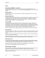
Resistor jumpers are used on the board to make the appropriate connections for either one or two
parts. The resistors are installed as listed in the following table.
SRAM Configuration Jumpers
SRAMs Configuration R101 R102 R103 R104
1
128K x 8
X
X
2
128K x 16
X
X
X – indicates installed 0 ohm resistor jumpers
EEPROM
The GX unit uses a non-volatile EEPROM device to store data, such as pilot name, address, phone
number, aircraft ID information, password and the GX unit serial number. Additionally, the EEPROM
stores configuration information such as +5 V calibration data, CDI and VDI calibration data.
The NAV board includes one 16 KBIT (2K x 8) parallel EEPROM, Atmel part no. AT28C16E. The
board layout also accepts an 8 K x 8 EEPROM, an AT26C64. The EEPROM is an 8-bit memory and
cannot be configured as a 16-bit memory.
Read access can be made from the EEPROM as a standard memory device. Write access can also
be made as a standard memory device, but note that there is a minimum period of 200 µsec between
writes. This period is for the internally timed programming cycle. During the programming cycle,
completion status can be read back from the device.
For more information on the EEPROM, refer to the Atmel Nonvolatile Memory Data Book.
PCMCIA Data Card Interface
All GX models utilize a Flybrary database stored on a standard plug-in PCMCIA FLASH memory card
for easy updating and replacement. Simply plug in the new datacard to update your existing database
or change to a new database.
Avionics Outputs
CDI/VDI Outputs
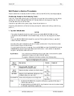
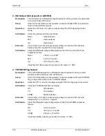
The GX50/60/65 units provide outputs to drive CDI and HSI indicators and an autopilot. These
outputs are to be connected as appropriate for the particular installation. The CDI/HSI outputs may be
connected to a dedicated CDI or HSI or to a shared indicator using an appropriate switching relay.
Flag Outputs
The GX units provide TO/OFF/FROM flag outputs.
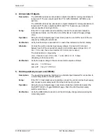
Annunciator Outputs
The GX55 provides MSG (message) and PTK (parallel track) annunciator outputs. In addition to
these two outputs, the GX50/60/65 units provide OBS/HLD (waypoint sequencing hold), APPRCH
(approach) and ACTIVE (approach active) annunciator outputs.
Altitude Input
The GX50/60/65 includes an altitude input, which is used for GPS RAIM calculations as well as
providing for altitude assist functions such as altitude preset and hold and 3D airspace alerts. The
Summary of Contents for APOLLO GX SERIES
Page 8: ...Garmin AT Rev viii GX Service Manual 2004 Garmin AT This Page Intentionally Left Blank...
Page 12: ...Garmin AT Rev 1 4 GX Service Manual 2004 Garmin AT...
Page 24: ...Garmin AT Rev 2 12 GX Service Manual 2004 Garmin AT...
Page 26: ...Garmin AT Rev 3 2 GX Service Manual 2004 Garmin AT...
Page 27: ...2004 Garmin AT GX Service Manual 4 1 Chapter 4 Antenna Installation Guides...
Page 28: ...Garmin AT Rev 4 2 GX Service Manual 2004 Garmin AT...
Page 32: ...Garmin AT Rev 5 4 GX Service Manual 2004 Garmin AT...
Page 96: ...Garmin AT Rev 7 58 GX Service Manual 2004 Garmin AT...
Page 98: ...Garmin AT Rev 8 2 GX Service Manual 2004 Garmin AT Figure 8 1 GX55 Assembly Board Locations...
Page 122: ...Garmin AT Rev 8 26 GX Service Manual 2004 Garmin AT...
Page 130: ...Garmin AT Rev 9 8 GX Service Manual 2004 Garmin AT...
Page 140: ...Garmin AT Rev 10 10 GX Service Manual 2004 Garmin AT Figure 10 5 Comm Board Block Diagram...
Page 152: ...Garmin AT Rev 10 22 GX Service Manual 2004 Garmin AT...
Page 158: ...Garmin AT Rev 11 6 GX Service Manual 2004 Garmin AT...
Page 160: ...Garmin AT Rev 12 2 GX Service Manual 2004 Garmin AT...
Page 162: ...Garmin AT Rev 13 2 GX Service Manual 2004 Garmin AT...
Page 165: ......
Page 166: ......

