Garmin AT
Rev --
© 2004 Garmin AT
GX Service Manual
7-9
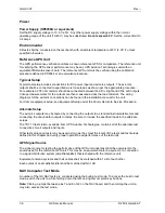
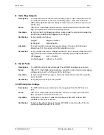
2. Seed Position, Time, and Date
Specification:
The GX includes a real time clock (RTC) for time and date information that must
be set after the system initialization. The seed time/date are required for
initialization of position sensors.
Operation:
During the normal operation startup sequence, enter the current date, time and
seed position on the Date/Time page, or go to the Date/Time page in system
mode and enter the current time, date, and seed position. Refer to the user’s
manual or installation manual.
Notes:
The GPS sensor requires the time, date, and position for proper startup. The
position can be selected from the database.
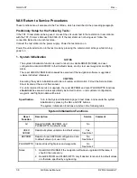
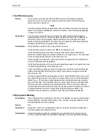
NAV Test Procedures
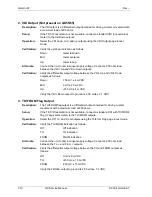
1. CDI Output
Description:
The CDI output is a differential output intended for driving a meter movement
with a maximum load of 200 ohms.
Setup:
If the TST-10 test station is not available, connect a standard CDI (or equivalent
meter) to the TO/FROM outputs.
Operation:
Select the CDI left, mid, and right outputs using the CDI Output page in test
mode.
Verification:
Verify the left/right indication as follows:
Left:
meter full left
Mid:
meter
centered
Right:
meter full right
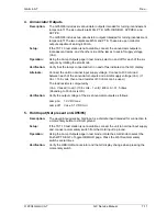
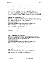
Alternate:
If the TST-10 test station is not available, connect the unit to nominal input supply
voltage. Connect a 200-ohm load between the CDI+ Right and CDI+ Left outputs.
Verification:
Verify the differential output voltage between the CDI+ Right and CDI+ Left
outputs as follows:
Left:
-150 mV ± 4 mVDC
Mid:
0 mV ± 2.0 mVDC
Right:
+150 mV ± 4 mVDC
Verify the CDI+ Left output to ground is 2.05 volts ± 0.1 VDC.
Summary of Contents for APOLLO GX SERIES
Page 8: ...Garmin AT Rev viii GX Service Manual 2004 Garmin AT This Page Intentionally Left Blank...
Page 12: ...Garmin AT Rev 1 4 GX Service Manual 2004 Garmin AT...
Page 24: ...Garmin AT Rev 2 12 GX Service Manual 2004 Garmin AT...
Page 26: ...Garmin AT Rev 3 2 GX Service Manual 2004 Garmin AT...
Page 27: ...2004 Garmin AT GX Service Manual 4 1 Chapter 4 Antenna Installation Guides...
Page 28: ...Garmin AT Rev 4 2 GX Service Manual 2004 Garmin AT...
Page 32: ...Garmin AT Rev 5 4 GX Service Manual 2004 Garmin AT...
Page 96: ...Garmin AT Rev 7 58 GX Service Manual 2004 Garmin AT...
Page 98: ...Garmin AT Rev 8 2 GX Service Manual 2004 Garmin AT Figure 8 1 GX55 Assembly Board Locations...
Page 122: ...Garmin AT Rev 8 26 GX Service Manual 2004 Garmin AT...
Page 130: ...Garmin AT Rev 9 8 GX Service Manual 2004 Garmin AT...
Page 140: ...Garmin AT Rev 10 10 GX Service Manual 2004 Garmin AT Figure 10 5 Comm Board Block Diagram...
Page 152: ...Garmin AT Rev 10 22 GX Service Manual 2004 Garmin AT...
Page 158: ...Garmin AT Rev 11 6 GX Service Manual 2004 Garmin AT...
Page 160: ...Garmin AT Rev 12 2 GX Service Manual 2004 Garmin AT...
Page 162: ...Garmin AT Rev 13 2 GX Service Manual 2004 Garmin AT...
Page 165: ......
Page 166: ......


