Garmin AT
Rev --
7-6
GX Service Manual
© 2004 Garmin AT
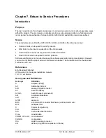
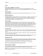
Power
Power Supply (HP6038A or equivalent)
Set the DC supply voltage to 13.8 V ± 5%. Any other power supply voltage within the normal
operating range of the unit (10-40 V) may be substituted.
Do not exceed 40 V.
Set the current limit to
3.2 amps.
Environmental
All tests shall be conducted on the test bench with an ambient temperature of 50
°
to 90
°
F unless
specified otherwise.
Reference GPS Unit
The GPS performance verification utilizes a known reference GPS for comparison. The reference unit
for verifying the GPS sensor performance may be any UPS Aviation Technologies unit with an
equivalent Motorola sensor board. The reference GPS unit must be verified using the calibration
procedure defined in PD0944 or an equivalent procedure.
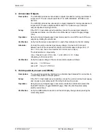
Typical Setup
Typical test setup includes connections for DC power input and avionics outputs. The avionics
outputs shall be connected to specified worst case loads as shown per the appropriate procedure.
For example a 200 ohm resistor should be connected between the CDI+ Right and CDI+ Left outputs.
Voltage measurements for the outputs are then measured across the load resistors. The wiring
diagrams for the avionics connections can be found in the installation manual for the unit.
For Comm equipment setup, see Equipment Setup under the Comm Return to Service Procedure.
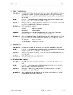
Alternate Setup
The avionics outputs may be tested by connecting the outputs to a standard instruments/meters and
connecting the annunciator outputs to lamps. Be sure to include the specified loads in the alternate
setups.
The TST 10 test station, available from UPS Aviation Technologies, contains all of the alternate test
connections for all outputs and inputs.
Other test setups and tests may be used as long as they meet the intent of the tests and test setups
defined in this chapter and verify proper operation and performance of the test units.
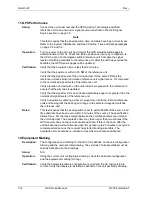
GPS Signal Source
The signal source for testing the performance of the GPS unit-under-test shall be equivalent to the
source used for the reference GPS unit. This may be an equivalent antenna system or a connection
to a signal distribution system (amplifier/splitter) that is shared with the reference unit.
Equivalent antenna systems and their cables shall be matched within 1 dB of each other.
Each output of an amplifier/splitter shall be matched within 1 dB.
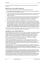
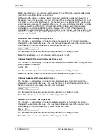
NAV Computer Test Mode
A number of the GX NAV tests are conducted using the built-in test mode. To access the built-in test
mode, switch the unit on while holding down the left- and right-most smart key buttons.
Note:
Placing a jumper between pins 7 and 8 of J2 on the NAV board, and then turning the unit on
may also access the test mode.
Summary of Contents for APOLLO GX SERIES
Page 8: ...Garmin AT Rev viii GX Service Manual 2004 Garmin AT This Page Intentionally Left Blank...
Page 12: ...Garmin AT Rev 1 4 GX Service Manual 2004 Garmin AT...
Page 24: ...Garmin AT Rev 2 12 GX Service Manual 2004 Garmin AT...
Page 26: ...Garmin AT Rev 3 2 GX Service Manual 2004 Garmin AT...
Page 27: ...2004 Garmin AT GX Service Manual 4 1 Chapter 4 Antenna Installation Guides...
Page 28: ...Garmin AT Rev 4 2 GX Service Manual 2004 Garmin AT...
Page 32: ...Garmin AT Rev 5 4 GX Service Manual 2004 Garmin AT...
Page 96: ...Garmin AT Rev 7 58 GX Service Manual 2004 Garmin AT...
Page 98: ...Garmin AT Rev 8 2 GX Service Manual 2004 Garmin AT Figure 8 1 GX55 Assembly Board Locations...
Page 122: ...Garmin AT Rev 8 26 GX Service Manual 2004 Garmin AT...
Page 130: ...Garmin AT Rev 9 8 GX Service Manual 2004 Garmin AT...
Page 140: ...Garmin AT Rev 10 10 GX Service Manual 2004 Garmin AT Figure 10 5 Comm Board Block Diagram...
Page 152: ...Garmin AT Rev 10 22 GX Service Manual 2004 Garmin AT...
Page 158: ...Garmin AT Rev 11 6 GX Service Manual 2004 Garmin AT...
Page 160: ...Garmin AT Rev 12 2 GX Service Manual 2004 Garmin AT...
Page 162: ...Garmin AT Rev 13 2 GX Service Manual 2004 Garmin AT...
Page 165: ......
Page 166: ......

