


Garmin AT
Rev --
© 2004 Garmin AT
GX Service Manual
7-23
Note:
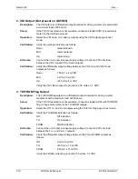
The RF signal strength is an 8-bit value with a range of 0 to 255 from the IF/RF AGC
voltage as read into the µcontroller through an A/D input.
Audio Noise Level Display
This function is used to display the noise level of the received audio.
NOISE 005
Note:
The noise level is an 8-bit value with a range of 0 to 255 from the noise level detector as
read into the µcontroller through an A/D input.
Headphone Level Display and Adjustment
This function is used to display and adjust the headphone audio level. Turning the small knob
changes the value. Setting the value to 0 slaves the headphone audio level to the volume control
knob. Setting to a non-zero value gives a fixed headphone audio level.
HphLv 015
Full transceiver functions are operational during this function, including transmit.
Note:
The headphone level is an 8-bit value with a range of 0 to 255.
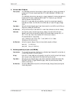
Microphone 1 Squelch (VOX)
This function is used to display the input level required to break squelch by microphone1.
Mic1 Sqlch 005
Note:
The VOX level is an 8-bit value with a range of 0 to 127 from the noise level detector as
read into the µcontroller through an A/D input.
Microphone 2 Squelch (VOX)
This function is used to display the input level required to break squelch by microphone2.
Mic2 Sqlch 005
Note:
The VOX level is an 8-bit value with a range of 0 to 127 from the noise level detector as
read into the µcontroller through an A/D input.
Transmit Mic
This function allows you to control which microphone is permitted to transmit. You may choose
Mic1, Mic2, or both.
MIC1+MIC2
Note:
The Transmit Mic will display MIC1, MIC2, or MIC1+MIC2.
Intercom Audio Level Display and Adjustment
This function is used to display and adjust the intercom audio level. Turning the small knob
changes the value. Setting the value to 0 slaves the intercom level to the volume control knob.
Setting to a non-zero value gives a fixed intercom audio level.
IcmLv 000
Full transceiver functions are operational during this function, including transmit.
Note:
The intercom level is an 8-bit value with a range of 0 to 255.
Summary of Contents for APOLLO GX SERIES
Page 8: ...Garmin AT Rev viii GX Service Manual 2004 Garmin AT This Page Intentionally Left Blank...
Page 12: ...Garmin AT Rev 1 4 GX Service Manual 2004 Garmin AT...
Page 24: ...Garmin AT Rev 2 12 GX Service Manual 2004 Garmin AT...
Page 26: ...Garmin AT Rev 3 2 GX Service Manual 2004 Garmin AT...
Page 27: ...2004 Garmin AT GX Service Manual 4 1 Chapter 4 Antenna Installation Guides...
Page 28: ...Garmin AT Rev 4 2 GX Service Manual 2004 Garmin AT...
Page 32: ...Garmin AT Rev 5 4 GX Service Manual 2004 Garmin AT...
Page 96: ...Garmin AT Rev 7 58 GX Service Manual 2004 Garmin AT...
Page 98: ...Garmin AT Rev 8 2 GX Service Manual 2004 Garmin AT Figure 8 1 GX55 Assembly Board Locations...
Page 122: ...Garmin AT Rev 8 26 GX Service Manual 2004 Garmin AT...
Page 130: ...Garmin AT Rev 9 8 GX Service Manual 2004 Garmin AT...
Page 140: ...Garmin AT Rev 10 10 GX Service Manual 2004 Garmin AT Figure 10 5 Comm Board Block Diagram...
Page 152: ...Garmin AT Rev 10 22 GX Service Manual 2004 Garmin AT...
Page 158: ...Garmin AT Rev 11 6 GX Service Manual 2004 Garmin AT...
Page 160: ...Garmin AT Rev 12 2 GX Service Manual 2004 Garmin AT...
Page 162: ...Garmin AT Rev 13 2 GX Service Manual 2004 Garmin AT...
Page 165: ......
Page 166: ......