Garmin AT
Rev --
7-12
GX Service Manual
© 2004 Garmin AT
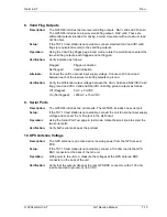
6. Sim Mode Input
Description:
The Sim Mode input is a discrete input intended for connection to a normally
closed momentary button to aircraft ground.
Setup:
If the TST-10 test station is not available, connect the unit to nominal input supply
and connect a normally closed momentary switch from the Hold input to ground.
A normally closed switch is required because when the pin is grounded, the unit
should come up in the normal mode. When the pin is ungrounded, or open, the
unit should come up in the Sim mode.
Operation:
Hold the Sim Mode switch on (electrically open) while turning on power to the
radio, then release the switch.
Verification:
Verify that the unit comes on in the Sim Mode when holding the momentary
switch and turning power on.
7. Super Flag Outputs (Not present on GX55/65)
Description:
The GX includes two high-level superflag outputs - NAV superflag and VDI
superflag. These outputs are open collector outputs capable of sourcing 400 mA
from the aircraft supply voltage (Vac) input supply. A valid condition is indicated
by the output source to the input supply.
Setup:
If the TST-10 test station is not available, connect the superflag outputs to
incandescent lamps, other side of lamps to ground.
Operation:
Using the Valid Flag Pages page in test mode, rotate the small knob to select the
two superflag outputs, each flagged and not flagged.
Verification:
Verify that the lamps connected turn on and off as indicated on the GX display.
The lamps should be off for flagged and on for not flagged.
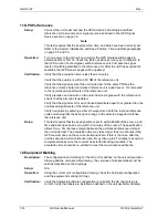
Alternate:
Connect the unit to nominal input supply voltage. Connect a 400 mA load
between each of the superflag outputs and ground. (If Vac = 13.6 volts, then a
load resistor of 33 ohms can be used.)
The load resistor is computed by:
(Vac - Vcesat) / Ioad = (13.6 volts - 1 volt) / 400 mA = 31.5 ohms.
(Rounding to 33 ohms is OK)
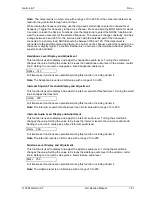
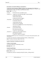
Verification:
Verify the output voltage of the two superflag outputs as follows:
Off (Flagged):
0 volts ± 0.2 VDC
On (Not flagged): Vac - 2.8 VDC min
Summary of Contents for APOLLO GX SERIES
Page 8: ...Garmin AT Rev viii GX Service Manual 2004 Garmin AT This Page Intentionally Left Blank...
Page 12: ...Garmin AT Rev 1 4 GX Service Manual 2004 Garmin AT...
Page 24: ...Garmin AT Rev 2 12 GX Service Manual 2004 Garmin AT...
Page 26: ...Garmin AT Rev 3 2 GX Service Manual 2004 Garmin AT...
Page 27: ...2004 Garmin AT GX Service Manual 4 1 Chapter 4 Antenna Installation Guides...
Page 28: ...Garmin AT Rev 4 2 GX Service Manual 2004 Garmin AT...
Page 32: ...Garmin AT Rev 5 4 GX Service Manual 2004 Garmin AT...
Page 96: ...Garmin AT Rev 7 58 GX Service Manual 2004 Garmin AT...
Page 98: ...Garmin AT Rev 8 2 GX Service Manual 2004 Garmin AT Figure 8 1 GX55 Assembly Board Locations...
Page 122: ...Garmin AT Rev 8 26 GX Service Manual 2004 Garmin AT...
Page 130: ...Garmin AT Rev 9 8 GX Service Manual 2004 Garmin AT...
Page 140: ...Garmin AT Rev 10 10 GX Service Manual 2004 Garmin AT Figure 10 5 Comm Board Block Diagram...
Page 152: ...Garmin AT Rev 10 22 GX Service Manual 2004 Garmin AT...
Page 158: ...Garmin AT Rev 11 6 GX Service Manual 2004 Garmin AT...
Page 160: ...Garmin AT Rev 12 2 GX Service Manual 2004 Garmin AT...
Page 162: ...Garmin AT Rev 13 2 GX Service Manual 2004 Garmin AT...
Page 165: ......
Page 166: ......


