Operating manual
CNC 8070
13.
SETUP ASSI
STANCE
The
ci
rc
ul
ar
it
y (
roundne
ss)
t
e
st
(S
OFT
V03.0
X
)
286
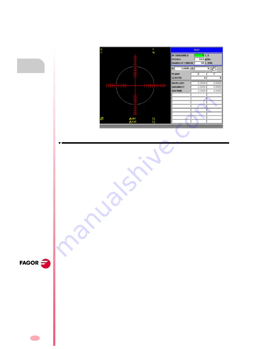
13.3.1 Interface description
The screen of the circularity test looks like this, with two clearly different parts. A
graphics window that shows the result of the test and a data area for interacting with
the system.
The graphics window
It is the area that shows, graphically, the result of the test.
The graphic shows the two moving axes and the theoretical circle of the interpolation
that will be carried out. As the test is being run, the positioning error at each point
is drawn on the circle. This error is shown projected radially.
Superimposed on the graphics, it shows the following additional data that is updated
by the CNC.
•
The real coordinates of the axes.
•
Programmed feedrate and % applied.
•
Diameter of the displayed circle.
•
Maximum and minimum error over the theoretical radius and angular position
where it has been detected.
Summary of Contents for CNC 8070
Page 1: ...CNC 8070 REF 0509 SOFT V03 0X OPERATING MANUAL Soft V03 0x Ref 0509...
Page 2: ......
Page 4: ......
Page 6: ......
Page 12: ......
Page 14: ......
Page 16: ......
Page 22: ......
Page 26: ......
Page 28: ......
Page 30: ......
Page 32: ......
Page 34: ......
Page 66: ...Operating manual CNC 8070 2 HOW TO OPERATE THE CNC Keyboard shortcuts SOFT V03 0X 32...
Page 96: ...Operating manual CNC 8070 3 AUTOMATIC MODE Program selection and execution SOFT V03 0X 62...
Page 194: ...Operating manual CNC 8070 7 MDI MODE Full MDI screen SOFT V03 0X 160...
Page 250: ...Operating manual CNC 8070 10 UTILITIES MODE Utilities Softkeys SOFT V03 0X 216...
Page 288: ...Operation manual 8070 CNC 11 PLC Messages service SOFT V03 0X 254...
Page 300: ...Operating manual CNC 8070 12 MACHINE PARAMETERS Operations with tables SOFT V03 0X 266...
Page 346: ...Operating manual CNC 8070 14 DDSSETUP Command generator SOFT V03 0X 312...


