


Maintenance 4. Cable
84
LS20 Rev.4
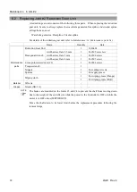
CAUTION
■
If the connectors have been disconnected during the replacement of the cable
unit, be sure to reconnect the connectors to their proper positions. Refer to the
block diagrams.
Improper connection of the connectors may result in improper function of the
robot system.
For details on the connections, refer to
Maintenance: 4.2 Wiring Diagrams.
■
When installing the cover, be careful not to allow the cables to interfere with the
cover mounting and do not bend these cables forcibly to push them into the
cover. Unnecessary strain on cables may result in damage to the cables,
disconnection, and/or contact failure. Damaged cables, disconnection, or
contact failure is extremely hazardous and may result in electric shock and/or
improper function of the robot system.
When routing the cables, observe the cable locations after removing the cover.
Be sure to place the cables back to their original locations.
■
Be sure to connect the cables properly. Do not allow unnecessary strain on the
cables. (Do not put heavy objects on the cables. Do not bend or pull the cables
forcibly.) The unnecessary strain on the cables may result in damage to the
cables, disconnection, and/or contact failure. Damaged cables, disconnection,
or contact failure is extremely hazardous and may result in electric shock and/or
improper function of the robot system.
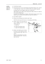
M/C Cable
Removal
(1) Turn OFF the Controller.
(2) Disconnect the power cable and signal cable connectors from the controller.
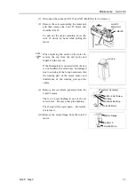
(3) Remove the ferrite core on the power cable.
The part will be used again. Be careful not
to lose it.
Ferrite core
Power cable
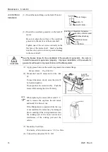
(4) Remove the Connector Plate.
For details, refer to
Maintenance: 3.4
Connector Plate
.
Do not pull the plate forcibly.
Signal Cable
: 1 connector
Power Cable
: 3 connectors
NOTE
Summary of Contents for LS20
Page 1: ...Rev 4 EM179R3533F SCARA ROBOT LS20 series MANIPULATOR MANUAL ...
Page 2: ...MANIPULATOR MANUAL LS20 series Rev 4 ...
Page 8: ...vi LS20 Rev 4 ...
Page 12: ...TABLE OF CONTENTS x LS20 Rev 4 ...
Page 14: ......
Page 29: ...Setup Operation 2 Specifications LS20 Rev 4 17 LS20 804S Standard Model ...
Page 31: ...Setup Operation 2 Specifications LS20 Rev 4 19 LS20 804C Cleanroom Model ...
Page 33: ...Setup Operation 2 Specifications LS20 Rev 4 21 LS20 A04S Standard Model ...
Page 35: ...Setup Operation 2 Specifications LS20 Rev 4 23 LS20 A04C Cleanroom Model ...
Page 72: ......
Page 92: ...Maintenance 4 Cable 80 LS20 Rev 4 4 2 Wiring Diagrams 4 2 1 Signal Cable ...
Page 176: ...Maintenance 14 Maintenance Parts List 164 LS20 Rev 4 ...