


Setup & Operation 4. Setting of End Effectors
LS20 Rev.4
41
4. Setting of End Effectors
4.1 Attaching an End Effector
Users are responsible for making their own end effector(s). Before attaching an end
effector, observe these guidelines.
CAUTION
■
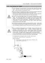
If you use an end effector equipped with a gripper or chuck, connect wires and/or
pneumatic tubes properly so that the gripper does not release the work piece
when the power to the robot system is turned OFF. Improper connection of the
wires and/or pneumatic tubes may damage the robot system and/or work piece
as the work piece is released when the Emergency Stop switch is pressed.
I/O outputs are configured at the factory so that they are automatically shut off (0)
by power disconnection, the Emergency Stop switch, or the safety features of the
robot system.
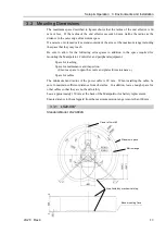
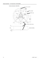
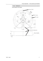
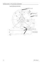
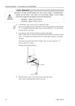
Shaft
- Attach an end effector to the lower end of the shaft.
For the shaft dimensions, and the overall dimensions of the Manipulator, refer to
Setup
& Operation: 2. Specifications
.
- Do not move the upper limit mechanical stop on the lower side of the shaft.
Otherwise, when “Jump motion” is performed, the upper limit mechanical stop may hit
the Manipulator, and the robot system may not function properly.
- Use a split muff coupling with an M4 bolt or larger to attach the end effector to the
shaft.
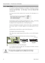
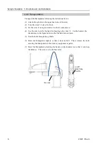
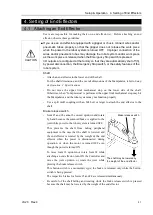
Brake release switch
- Joint #3 and #4 cannot be moved up/down and rotate
by hand because the solenoid brake is applied to the
joint while power to the robot system is turned OFF.
This prevents the shaft from hitting peripheral
equipment in the case that the shaft is lowered and
the end effector is rotated by the weight of the end
effector when the power is disconnected during
operation, or when the motor is turned OFF even
though the power is turned ON.
To move Joint #3 up/down or rotate Joint #4 while
attaching an end effector, turn ON the Controller and
move the joint up/down or rotate the joint while
pressing the brake release switch.
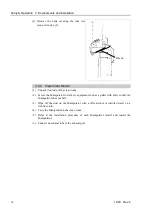
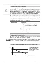
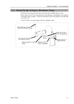
Brake release switch
The shaft may be lowered by
the weight of the end effector.
This button switch is a momentary-type; the brake is released only while the button
switch is being pressed.
The respective brakes for Joints #3 and #4 are released simultaneously.
- Be careful of the shaft falling and rotating while the brake release switch is pressed
because the shaft may be lowered by the weight of the end effector.
Summary of Contents for LS20
Page 1: ...Rev 4 EM179R3533F SCARA ROBOT LS20 series MANIPULATOR MANUAL ...
Page 2: ...MANIPULATOR MANUAL LS20 series Rev 4 ...
Page 8: ...vi LS20 Rev 4 ...
Page 12: ...TABLE OF CONTENTS x LS20 Rev 4 ...
Page 14: ......
Page 29: ...Setup Operation 2 Specifications LS20 Rev 4 17 LS20 804S Standard Model ...
Page 31: ...Setup Operation 2 Specifications LS20 Rev 4 19 LS20 804C Cleanroom Model ...
Page 33: ...Setup Operation 2 Specifications LS20 Rev 4 21 LS20 A04S Standard Model ...
Page 35: ...Setup Operation 2 Specifications LS20 Rev 4 23 LS20 A04C Cleanroom Model ...
Page 72: ......
Page 92: ...Maintenance 4 Cable 80 LS20 Rev 4 4 2 Wiring Diagrams 4 2 1 Signal Cable ...
Page 176: ...Maintenance 14 Maintenance Parts List 164 LS20 Rev 4 ...