


Maintenance 6. Arm #2
96
LS20 Rev.4
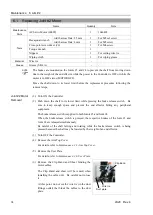
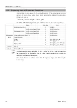
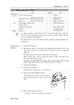
Joint #2 Motor
Installation
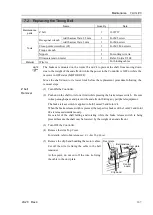
(1) Mount the motor flange on the Joint #2 motor.
Motor Flange
Joint #2 Motor
2-M5
×
15
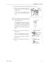
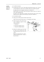
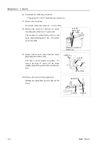
(2) Mount the waveform generator on the Joint #2
motor.
Be sure to align the end face of the waveform
generator to the end face of the motor shaft.
Tighten one of the set screws vertically on the
flat face of the motor shaft. Insert a bushing
into the other set screw hole to prevent damage
to the motor shaft.
2-M5×8 set screw
M5 Brass Bushing
Joint #2 Motor
End face of Waveform Generator
End face of Motor shaft
O ring
CAUTION
■
See the figures above for the orientation of the waveform generator. Be sure to
install the waveform generator properly. Improper installation of the waveform
generator will result in improper function of the Manipulator.
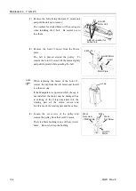
(3) Apply grease between the waveform generator and motor flange.
Grease volume : 38 g (SK-1A)
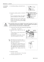
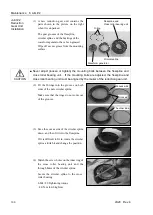
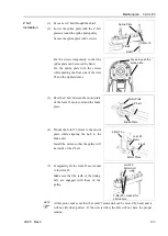
(4) Mount the Joint #2 motor unit on the Arm
#2.
To insert the motor, slowly move the Arm #2
by hand and push in.
Do not push in the motor forcibly. Push the
motor while moving the Arm #2 slowly.
4-M5
×
20
Joint #2
Motor Unit
Arm #2
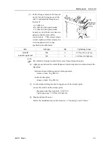
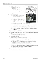
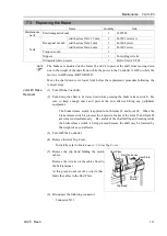
When replacing the motor of the Joint # 2, 3,
and 4, remove the cap from the old motor
and install it to the new one.
If the Manipulator is operated while the cap
is not installed, the motor may be damaged
due to entering of the foreign materials into
the rotating part of the motor sensor and
interference of the rotating part and the
cables.
cap
(5) Mount the User Plate.
For details, refer to
Maintenance: 3.6 User Plate
.
(6) Connect the connectors: X221, X21.
NOTE
Summary of Contents for LS20
Page 1: ...Rev 4 EM179R3533F SCARA ROBOT LS20 series MANIPULATOR MANUAL ...
Page 2: ...MANIPULATOR MANUAL LS20 series Rev 4 ...
Page 8: ...vi LS20 Rev 4 ...
Page 12: ...TABLE OF CONTENTS x LS20 Rev 4 ...
Page 14: ......
Page 29: ...Setup Operation 2 Specifications LS20 Rev 4 17 LS20 804S Standard Model ...
Page 31: ...Setup Operation 2 Specifications LS20 Rev 4 19 LS20 804C Cleanroom Model ...
Page 33: ...Setup Operation 2 Specifications LS20 Rev 4 21 LS20 A04S Standard Model ...
Page 35: ...Setup Operation 2 Specifications LS20 Rev 4 23 LS20 A04C Cleanroom Model ...
Page 72: ......
Page 92: ...Maintenance 4 Cable 80 LS20 Rev 4 4 2 Wiring Diagrams 4 2 1 Signal Cable ...
Page 176: ...Maintenance 14 Maintenance Parts List 164 LS20 Rev 4 ...