


Maintenance 10. Ball Screw Spline Unit
LS20 Rev.4
131
10. Ball Screw Spline Unit
WARNING
■
Do not insert or pull out the motor connectors while the power to the robot system
is turned ON. Inserting or pulling out the motor connectors with the power ON is
extremely hazardous and may result in serious bodily injury as the Manipulator
may move abnormally, and also may result in electric shock and/or malfunction of
the robot system.
■
To shut off power to the robot system, pull out the power plug from the power
source. Be sure to connect the AC power cable to a power receptacle. DO
NOT connect it directly to a factory power source.
■
Before performing any replacement procedure, turn OFF the Controller and
related equipment, and then pull out the power plug from the power source.
Performing any replacement procedure with the power ON is extremely
hazardous and may result in electric shock and/or malfunction of the robot
system.
After
parts have been replaced (motors, reduction gear units, brakes, timing belts, ball
screw spline unit, etc.), the Manipulator cannot operate properly because a mismatch
exists between the origin stored in each motor and its corresponding origin stored in the
Controller.
After replacing the parts, it is necessary to match these origins.
The process of aligning the two origins is called “Calibration”.
Refer to
Maintenance: 13. Calibration
to perform the calibration.
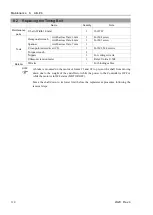
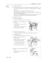
10.1 Greasing the Ball Screw Spline Unit
Name
Quantity
Note
Grease
For Ball Screw Spline Unit (AFB grease)
Proper
quantity -
Tools
Wiping cloth
1
For wiping grease (Spline shaft)
Cross-point screwdriver
1
For clamp band removal
Only for Cleanroom-model
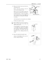
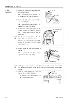
The brake release switch affects both Joints #3 and #4. When the brake release switch is
pressed in emergency mode, the brake for both Joints #3 and #4 are released simultaneously.
Be careful of the shaft falling and rotating while the brake release switch is pressed because
the shaft may be lowered by the weight of an end effector.
NOTE
NOTE
Summary of Contents for LS20
Page 1: ...Rev 4 EM179R3533F SCARA ROBOT LS20 series MANIPULATOR MANUAL ...
Page 2: ...MANIPULATOR MANUAL LS20 series Rev 4 ...
Page 8: ...vi LS20 Rev 4 ...
Page 12: ...TABLE OF CONTENTS x LS20 Rev 4 ...
Page 14: ......
Page 29: ...Setup Operation 2 Specifications LS20 Rev 4 17 LS20 804S Standard Model ...
Page 31: ...Setup Operation 2 Specifications LS20 Rev 4 19 LS20 804C Cleanroom Model ...
Page 33: ...Setup Operation 2 Specifications LS20 Rev 4 21 LS20 A04S Standard Model ...
Page 35: ...Setup Operation 2 Specifications LS20 Rev 4 23 LS20 A04C Cleanroom Model ...
Page 72: ......
Page 92: ...Maintenance 4 Cable 80 LS20 Rev 4 4 2 Wiring Diagrams 4 2 1 Signal Cable ...
Page 176: ...Maintenance 14 Maintenance Parts List 164 LS20 Rev 4 ...