


Maintenance 13. Calibration
158
LS20 Rev.4
13.4 Calibration Procedure without using Calibration Wizard
This section indicates the calibration without using the calibration wizard of EPSON RC+.
For details of calibration using the calibration wizard, refer to
Maintenance: 13.2
Calibration Procedure
.
When coordinates for the Manipulator working point require calculation, it is important
for Joint #2 to be calibrated accurately. Execute the procedure in “Calibration Using
Right / Left Arm Orientations” to accurately calibrate Joint #2. For details, refer to
Maintenance: 13.3 Accurate Calibration of Joint #2
.
You cannot calibrate Joint #4 alone because of the structure of the Manipulator. When
calibrating Joint #4, you must calibrate Joint #3 and #4 at the same time.
The reference point (a point to identify the position of the manipulator) needs to be
specified for calibration.
Follow steps 1 to 6 described below in order to calibrate the origin.
1. Basic Pose Confirmation
(1)-1 After the part replacement, execute the calibration using the point data
currently registered.
Confirm the point data number (P*) to reconstruct the correct manipulator
position.
* Point data before the parts replacement (motor, reduction gear, belt, etc.) is
necessary for the calibration.
2. Part Replacement
(2)-1 Replace parts as dictated by this manual.
* Be careful not to injure yourself or damage parts during part replacement.
3. Encoder Initialization
(3)-1 Turn ON the Controller when all joints are in the motion range.
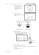
(3)-2 Manually move the joint that needs origin alignment to its approximate 0 pulse
position.
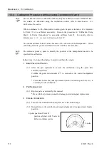
0 pulse position of Joint #1:
position aligned with X-axis in
Robot coordinate system
0 pulse
+
−
NOTE
NOTE
Summary of Contents for LS20
Page 1: ...Rev 4 EM179R3533F SCARA ROBOT LS20 series MANIPULATOR MANUAL ...
Page 2: ...MANIPULATOR MANUAL LS20 series Rev 4 ...
Page 8: ...vi LS20 Rev 4 ...
Page 12: ...TABLE OF CONTENTS x LS20 Rev 4 ...
Page 14: ......
Page 29: ...Setup Operation 2 Specifications LS20 Rev 4 17 LS20 804S Standard Model ...
Page 31: ...Setup Operation 2 Specifications LS20 Rev 4 19 LS20 804C Cleanroom Model ...
Page 33: ...Setup Operation 2 Specifications LS20 Rev 4 21 LS20 A04S Standard Model ...
Page 35: ...Setup Operation 2 Specifications LS20 Rev 4 23 LS20 A04C Cleanroom Model ...
Page 72: ......
Page 92: ...Maintenance 4 Cable 80 LS20 Rev 4 4 2 Wiring Diagrams 4 2 1 Signal Cable ...
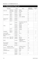
Page 176: ...Maintenance 14 Maintenance Parts List 164 LS20 Rev 4 ...