


Maintenance 8. Arm #4
LS20 Rev.4
123
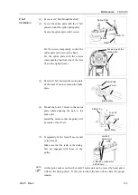
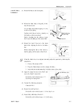
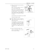
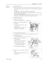
(6) Loosely secure the Joint #4 motor unit to
the Arm #2.
Make sure the teeth of the timing belt are
engaged with those of the pulley.
At this point, make sure that the Joint #4
motor unit can be moved by hand, and it
will not tilt when pulled. If the unit is
tilted, the belt will not have the proper
tension.
3-M5×20
+ washer for
slotted hole
Joint #4
Motor Unit
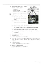
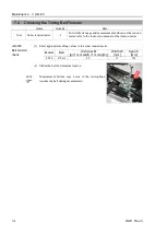
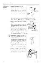
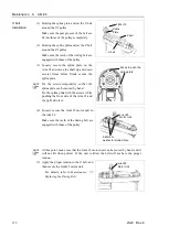
(7) Apply the proper tension to the U belt,
and then secure the Joint #4 motor unit.
U belt tension
: 206N (21.0
±
0.75 kgf)
Axial tension (if being pulled): 412 N
To apply tension to the Joint #4 motor
unit, use the bolt at the front of the plate.
M4 Bolt
Joint #4
Motor Unit
Plate
M4 Nut
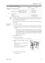
(7-1) Loosen the nut and turn the bolt.
Push in the Joint #4 motor unit
plate slowly.
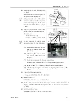
(7-2) After fixing the Joint #4 motor
unit, turn the bolt to leave from
the plate.
(7-3) Check the tension using the ultrasonic tension meter.
For details, refer to
Maintenance 8.5 Checking the Timing Belt Tension
.
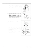
(7-4) Repeat the steps (7)-1 through (7)-3 until you get appropriate tension.
(7-5) After the adjustment, put the bolt back to its original position and fix it with
the nut.
(8) Connect the following connectors.
Connector: X231, X241, X31, X35, X41, X42
(9) Mount the User Plate.
For details, refer to
Maintenance: 3.6 User Plate
.
(10) Bind the cables with new wire ties at their original positions as before in the removal
step (5). Bind the cables with the clip band. Do not allow unnecessary strain on
the cables.
(11) Install the Arm Top Cover.
For details, refer to
Maintenance: 3.1 Arm Top Cover
.
NOTE
NOTE
Summary of Contents for LS20
Page 1: ...Rev 4 EM179R3533F SCARA ROBOT LS20 series MANIPULATOR MANUAL ...
Page 2: ...MANIPULATOR MANUAL LS20 series Rev 4 ...
Page 8: ...vi LS20 Rev 4 ...
Page 12: ...TABLE OF CONTENTS x LS20 Rev 4 ...
Page 14: ......
Page 29: ...Setup Operation 2 Specifications LS20 Rev 4 17 LS20 804S Standard Model ...
Page 31: ...Setup Operation 2 Specifications LS20 Rev 4 19 LS20 804C Cleanroom Model ...
Page 33: ...Setup Operation 2 Specifications LS20 Rev 4 21 LS20 A04S Standard Model ...
Page 35: ...Setup Operation 2 Specifications LS20 Rev 4 23 LS20 A04C Cleanroom Model ...
Page 72: ......
Page 92: ...Maintenance 4 Cable 80 LS20 Rev 4 4 2 Wiring Diagrams 4 2 1 Signal Cable ...
Page 176: ...Maintenance 14 Maintenance Parts List 164 LS20 Rev 4 ...