


Maintenance 10. Ball Screw Spline Unit
LS20 Rev.4
135
10.2 Replacing the Ball Screw Spline Unit
A brake is mounted on the motor of Joints #3 and #4 to prevent the shaft from moving
down due to the weight of the end effector while the power to the Controller is OFF or
while the motor is in OFF status (MOTOR OFF).
Move the shaft down to its lower limit before the replacement procedure following the
removal steps.
Name
Quantity
Note
Maintenance
parts
Ball Screw Spline Unit
1
Each manipulator model
(Refer to
Maintenance:
14. Maintenance parts
)
For Ball Screw Spline Unit (AFB grease)
Proper
quantity 6012557
Tools
Hexagonal wrench
width across flats: 3 mm
1
For M4 screw
width across flats: 4 mm
1
For M5 screw
Torque wrench
1
Nippers
1
For cutting wire tie
Cross-point screwdriver (#2)
1
Wiping cloth
1
For wiping grease (Spline shaft)
Material
Wire tie
-
Grease
For Ball Screw Spline Unit (AFB grease)
Proper
quantity -
Ball Screw
Spline Unit
Removal
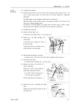
(1) Turn ON the Controller.
(2) Push down the shaft to its lower limit while pressing the brake release switch. Be
sure to keep enough space and prevent the end effector hitting any peripheral
equipment.
The brake release switch is applied to both Joints #3 and Joint #4.
When the brake release switch is pressed, the respective brakes of the Joint #3 and
Joint #4 are released simultaneously.
Be careful of the shaft falling and rotating while the brake release switch is being
pressed because the shaft may be lowered by the weight of an end effector.
(3) Turn OFF the Controller.
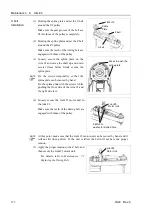
(4) Detach the wires/tubes from the end effector, and remove the end effector.
(5) This step is only for Cleanroom-model.
Remove the bellows. For details, refer to
Maintenance: 9. Bellows
.
(6) Remove the Arm Top Cover and Arm Bottom Cover.
For details, refer to
Maintenance: 3. Covers
.
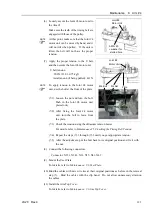
(7) Remove the following.
Joint #3 motor unit, Joint #4 motor unit
For details, refer to
Maintenance: 7.1 Replacing Joint #3 Motor s
.
Maintenance:8.1 Replacing Joint #4 Motor s
.
NOTE
Summary of Contents for LS20
Page 1: ...Rev 4 EM179R3533F SCARA ROBOT LS20 series MANIPULATOR MANUAL ...
Page 2: ...MANIPULATOR MANUAL LS20 series Rev 4 ...
Page 8: ...vi LS20 Rev 4 ...
Page 12: ...TABLE OF CONTENTS x LS20 Rev 4 ...
Page 14: ......
Page 29: ...Setup Operation 2 Specifications LS20 Rev 4 17 LS20 804S Standard Model ...
Page 31: ...Setup Operation 2 Specifications LS20 Rev 4 19 LS20 804C Cleanroom Model ...
Page 33: ...Setup Operation 2 Specifications LS20 Rev 4 21 LS20 A04S Standard Model ...
Page 35: ...Setup Operation 2 Specifications LS20 Rev 4 23 LS20 A04C Cleanroom Model ...
Page 72: ......
Page 92: ...Maintenance 4 Cable 80 LS20 Rev 4 4 2 Wiring Diagrams 4 2 1 Signal Cable ...
Page 176: ...Maintenance 14 Maintenance Parts List 164 LS20 Rev 4 ...