


Maintenance 6. Arm #2
LS20 Rev.4
99
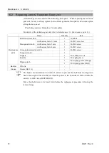
Joint #2
Reduction
Gear Unit
Removal
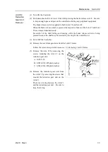
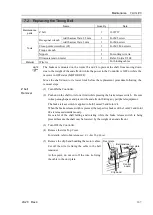
(1) Turn ON the Controller.
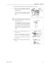
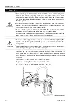
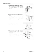
(2) Push down the shaft to its lower limit while pressing the brake release switch. Be sure
to keep enough space and prevent the end effector hitting any peripheral equipment.
The brake release switch is applied to both Joints #3 and Joint #4.
When the brake release switch is pressed, the respective brakes of the Joint #3 and Joint
#4 are released simultaneously.
Be careful of the shaft falling and rotating while the brake release switch is being
pressed because the shaft may be lowered by the weight of an end effector.
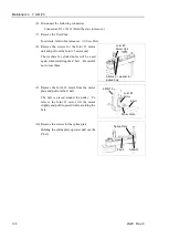
(3) Turn OFF the Controller.
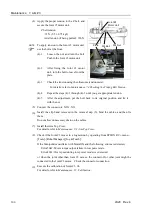
(4) Remove the waveform generator from the Joint #2 motor.
Follow the removal steps in
Maintenance: 6.1 Replacing Joint #2 Motor
.
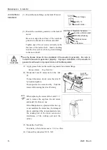
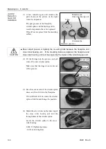
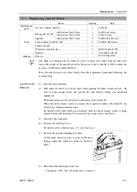
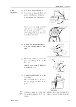
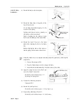
(5) Remove the Arm #2 by removing the
screws mounting the Arm #2 on the
reduction gear unit.
A: 16-M5
×
30
B: 8-M5
×
45+8-M5 plain washer
C: 4-M4
×
20+4-M4 plain washer
A
Arm #2
Reduction
Gear Unit
Arm #1
B
C
O-ring
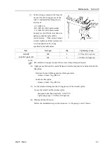
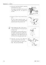
(6) Remove the reduction gear unit from
the Arm #1 by removing the screws that
mounts the reduction gear unit on the
Arm #1.
There is an O-ring between the Arm #1
and the reduction gear unit. Be sure to
keep the O-ring.
Summary of Contents for LS20
Page 1: ...Rev 4 EM179R3533F SCARA ROBOT LS20 series MANIPULATOR MANUAL ...
Page 2: ...MANIPULATOR MANUAL LS20 series Rev 4 ...
Page 8: ...vi LS20 Rev 4 ...
Page 12: ...TABLE OF CONTENTS x LS20 Rev 4 ...
Page 14: ......
Page 29: ...Setup Operation 2 Specifications LS20 Rev 4 17 LS20 804S Standard Model ...
Page 31: ...Setup Operation 2 Specifications LS20 Rev 4 19 LS20 804C Cleanroom Model ...
Page 33: ...Setup Operation 2 Specifications LS20 Rev 4 21 LS20 A04S Standard Model ...
Page 35: ...Setup Operation 2 Specifications LS20 Rev 4 23 LS20 A04C Cleanroom Model ...
Page 72: ......
Page 92: ...Maintenance 4 Cable 80 LS20 Rev 4 4 2 Wiring Diagrams 4 2 1 Signal Cable ...
Page 176: ...Maintenance 14 Maintenance Parts List 164 LS20 Rev 4 ...