


Maintenance 13. Calibration
148
LS20 Rev.4
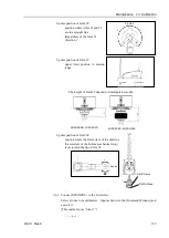
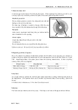
0 pulse position of Joint #1:
position aligned with X-axis in
Robot coordinate system
0 pulse
+
−
0 pulse position of Joint #2:
position where Arms #1 and #2
are in a straight line
(Regardless of the Joint #1
direction.)
0 pulse
+
−
0 pulse position of Joint #3:
upper limit position in motion
range
The height of Joint #3 depends on
manipulator model.
LS20-804S, LS20-A04S
LS20-804C, LS20-A04C
0 pulse position of Joint #4:
position where the flat surface of the shaft (or
the set screw of the bottom mechanical stop)
faces toward the tip of Arm #2.
0 pulse
+
−
Set Screws
Flat Surface
Summary of Contents for LS20
Page 1: ...Rev 4 EM179R3533F SCARA ROBOT LS20 series MANIPULATOR MANUAL ...
Page 2: ...MANIPULATOR MANUAL LS20 series Rev 4 ...
Page 8: ...vi LS20 Rev 4 ...
Page 12: ...TABLE OF CONTENTS x LS20 Rev 4 ...
Page 14: ......
Page 29: ...Setup Operation 2 Specifications LS20 Rev 4 17 LS20 804S Standard Model ...
Page 31: ...Setup Operation 2 Specifications LS20 Rev 4 19 LS20 804C Cleanroom Model ...
Page 33: ...Setup Operation 2 Specifications LS20 Rev 4 21 LS20 A04S Standard Model ...
Page 35: ...Setup Operation 2 Specifications LS20 Rev 4 23 LS20 A04C Cleanroom Model ...
Page 72: ......
Page 92: ...Maintenance 4 Cable 80 LS20 Rev 4 4 2 Wiring Diagrams 4 2 1 Signal Cable ...
Page 176: ...Maintenance 14 Maintenance Parts List 164 LS20 Rev 4 ...