


Maintenance 10. Ball Screw Spline Unit
130
LS20 Rev.4
Bellows
Installation
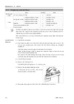
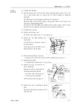
(1) To attach the upper bellows, move the shaft to its lower limit.
To attach the lower bellows, move the shaft to its upper limit.
To move the shaft up/down, press and hold the brake release switch.
Be sure to keep enough space and prevent the end effector hitting any peripheral
equipment.
The brake release switch is applied to both Joints #3 and Joint #4.
When the brake release switch is pressed, the respective brakes of the Joint #3 and
Joint #4 are released simultaneously.
Be careful of the shaft falling and rotating while the brake release switch is being
pressed because the shaft may be lowered by the weight of an end effector.
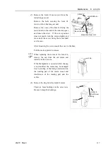
(2) Pass the shaft through the bellows from the larger joint.
(3) Secure the cover side of the bellows.
The bellows has two joints:
The larger joint must be attached to the cover
side.
The smaller joint must be attached to the end
face side of the shaft.
Attach the mounting part of the bellows until
the end touches the cylindrical part of the cover.
Then, secure them with clamp bands.
Upper bellows
cover side
Bottom bellows
cover side
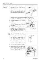
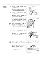
(4) Secure the shaft edge side of the bellows.
Cover the bearing case (black) on the edge of
the shaft with the bellows mounting part.
Then, secure them with clamp bands.
Upper bellows
shaft edge
Bottom bellows
Shaft edge
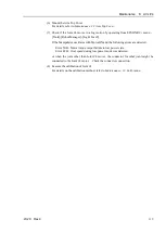
(5) When completed the bellows installation, check that the bellows stretch smoothly
without any excessive force by moving the shaft up/down by hand and rotating the
Joint #4.
(6) Turn OFF the Controller and peripheral equipment.
(7) Attach the end effector.
(8) Connect the cables and tubes to the end effector.
Summary of Contents for LS20
Page 1: ...Rev 4 EM179R3533F SCARA ROBOT LS20 series MANIPULATOR MANUAL ...
Page 2: ...MANIPULATOR MANUAL LS20 series Rev 4 ...
Page 8: ...vi LS20 Rev 4 ...
Page 12: ...TABLE OF CONTENTS x LS20 Rev 4 ...
Page 14: ......
Page 29: ...Setup Operation 2 Specifications LS20 Rev 4 17 LS20 804S Standard Model ...
Page 31: ...Setup Operation 2 Specifications LS20 Rev 4 19 LS20 804C Cleanroom Model ...
Page 33: ...Setup Operation 2 Specifications LS20 Rev 4 21 LS20 A04S Standard Model ...
Page 35: ...Setup Operation 2 Specifications LS20 Rev 4 23 LS20 A04C Cleanroom Model ...
Page 72: ......
Page 92: ...Maintenance 4 Cable 80 LS20 Rev 4 4 2 Wiring Diagrams 4 2 1 Signal Cable ...
Page 176: ...Maintenance 14 Maintenance Parts List 164 LS20 Rev 4 ...