


shown as bits in
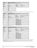
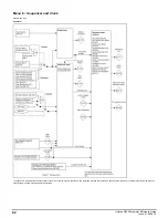
Enable Conditions
(06.010) as given in the table below.
Enable Conditions
(06.010) bits
Enable condition
0
Hardware Enable
(06.029)
1
Drive Enable
(06.015)
2
0 if auto tune completed or trip during auto-tune, but drive needs to be disabled and re-enabled
3
Reserved
4
Reserved
5
Zero until the drive thermal model has obtained temperatures from all drive thermistors at least once
6
Zero until all option modules that are present in the drive have indicated that they are ready to run or the system
has timed out waiting for this.
7
Reserved
8-10
Reserved
11
Zero if the drive is in standby mode. See
Standby Mode Enable
(06.060)
Because of the limited number of segments on drives with an LED display, these drives will indicate the parameter value as a decimal value rather
than a binary value.
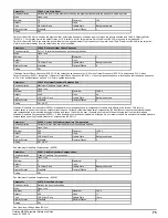
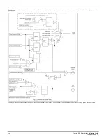
Parameter
06.011
Sequencer State Machine Inputs
Short description
Displays the states of inputs into the sequencer state machine
Mode
Open
‑
loop
Minimum
0
(Display: 0000000)
Maximum
127
(Display: 1111111)
Default
Units
Type
8 Bit Volatile
Update Rate
4ms
Display Format
Binary
Decimal Places
0
Coding
RO, ND, NC, PT, BU
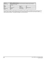
The bits in
Sequencer State Machine Inputs
(06.011) show the state of the inputs to the sequencer state machine as given in the tables below:
Sequencer State Machine Inputs
(06.011)
bits
Signal
Indicates
0
Final drive enable
The drive inverter is allowed to be enabled.
1
Final drive run
The motor can move away from standstill.
2
Under Voltage Active
(10.016)
The under voltage condition has been detected.
3
Zero Frequency
(10.003)
Indicated when the motor has stopped.
4
Drive tripped
The drive is tripped.
5
Limit switch active
(10.066)
Limit switch is active
6
Supply Loss
(10.015)
Supply loss condition has been detected.
Because of the limited number of segments on drives with an LED display, these drives will indicate the parameter value as a decimal value rather
than a binary value.
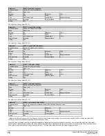
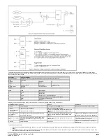
Parameter
06.012
Enable Stop Key
Short description
Set to 1 to enable the use of the stop key
Mode
Open
‑
loop
Minimum
0
Maximum
1
Default
0
Units
Type
1 Bit User Save
Update Rate
Background read
Display Format
Standard
Decimal Places
0
Coding
RW
The Stop key can be used to stop the drive if
Enable Stop Key
(06.012) = 1 or Keypad command is selected (see
Reference Selector
(01.014)).
If
Enable Stop Key
(06.012)= 0 and Keypad command is not selected. The Stop key is not active and can be used to initiate a drive reset without stopping the drive from running.
If
Enable Stop Key
(06.012) = 1 or Keypad command is selected, the drive reset can be initiated without stopping the drive by holding the Run key and then pressing the Stop key.
The Stop key is also used to reset the drive from the keypad.
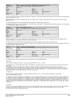
It should be noted that if the drive is tripped and is then reset from any source other than the keypad Stop key then the drive may start immediately under the following conditions:
1.
Enable Sequencer Latching
(06.040) = 0, the Final drive enable is active and one of the sequencer bits (
Run Forward
(06.030),
Run Reverse
(06.032) or
Run
(06.034) is active.
2.
Enable Sequencer Latching
(06.040) = 1, the Final drive enable is active,
Not Stop
(06.039) is active and one of the sequencer bits (
Run Forward
(06.030),
Run Reverse
(06.032) or
Run
(06.034) is active.
The drive sequencer has been designed so that pressing the Stop key, whatever the value of
Enable Stop Key
(06.012) or the Command Selection, does not make the drive state change from
stopped to running. As pressing the Stop key could reset a drive trip which could then restart the drive, the run output from the sequencer is held off until the following conditions are met when
the drive is tripped and the Stop key is pressed.
1.
Run Forward
(06.030) = 0 and
Run Reverse
(06.032) = 0 and
Run
(06.034) = 0*
2. OR
Run Forward
(06.030) = 1 and
Run Reverse
(06.032) = 1 for at least 60ms*
3. OR The Final drive enable = 0
4. OR The sequencer is in the UNDER_VOLTAGE state
5. OR If
Enable Sequencer Latching
(06.040) = 1,
Not Stop
(06.039) = 0
* If
Enable Sequencer Latching
(06.040) = 1 then the state of these sequencer bits must be 0 at the output of their latches.
Once the necessary conditions have been met the drive can then be restarted by activating the necessary bits for a normal start.
Parameter
06.013
Enable Auxiliary Key
Short description
Defines the behaviour of the drive when the auxilliary button is pressed
Mode
Open
‑
loop
Minimum
0
Maximum
2
Default
0
Units
Type
8 Bit User Save
Update Rate
Background read
Display Format
Standard
Decimal Places
0
Coding
RW, TE
88
Unidrive M200 Parameter Reference Guide
Issue: 01.05.00.10
Summary of Contents for unidrive m200
Page 1: ...Parameter Reference Guide Unidrive M200 Open loop Mode Issue 01 05 00 10 ...
Page 30: ...30 Unidrive M200 Parameter Reference Guide Issue 01 05 00 10 ...
Page 83: ...Enable logic Unidrive M200 Parameter Reference Guide Issue 01 05 00 10 83 ...
Page 125: ...Unidrive M200 Parameter Reference Guide Issue 01 05 00 10 125 ...
Page 145: ...Unidrive M200 Parameter Reference Guide Issue 01 05 00 10 145 ...
Page 204: ...204 Unidrive M200 Parameter Reference Guide Issue 01 05 00 10 ...


