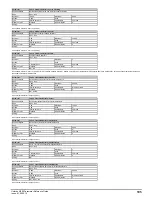


Parameter
14.001
PID1 Output
Short description
Displays the output for PID1
Mode
Open
‑
loop
Minimum
-100.00
Maximum
100.00
Default
Units
%
Type
16 Bit Volatile
Update Rate
4ms write
Display Format
Standard
Decimal Places
2
Coding
RO, ND, NC, PT
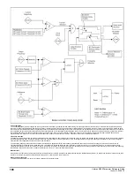
Controller
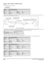
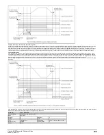
The controller section for the PID controller is shown in the introduction. If the enable is active the PID controller is active even if the destination is not routed to a valid parameter or set
to 0.000. It should be noted that if either of the enable sources is routed to 0.000 or to a non-valid parameter the source value is taken as 1, therefore with default settings,
PID1 Enable Source 1
(14.009) = 0.000 and
PID1 Enable Source 2
(14.027) = 0.000, the PID controller can be enabled by simply setting
PID1 Enable
(14.008).
PID1 Error
(14.022) is the difference between the reference and feedback produced by the reference and feedback systems described in
PID1 Reference Source
(14.003)
and
PID1 Feedback Source
(14.004). The PID controller output is defined as follows:
PID1 Output
(14.001) =
PID1 Error
(14.022) x [Kp + Ki/s + sKd/(0.064s + 1)]
Kp =
PID1 Proportional Gain
(14.010)
Ki =
PID1 Integral Gain
(14.011)
Kd =
PID1 Differential Gain
(14.012)
Therefore:
1. If
PID1 Error
(14.022) = 100.00% the proportional term gives a value of 100.00% if
PID1 Proportional Gain
(14.010) = 1.000.
2. If
PID1 Error
(14.022) = 100.00% the integral term gives a value that increases linearly by 100.00% per second if
PID1 Integral Gain
(14.011) = 1.000.
3. If
PID1 Error
(14.022) increases linearly by 100.00% per second the differential term gives a value of 100.00% if
PID1 Differential Gain
(14.012) = 1.000. (A filter with a time
constant of 64ms is provided on the differential term to reduce the noise produced by this term).
The output may be limited to a range that is less than the maximum range of
PID1 Output
(14.001) using
PID1 Output Upper Limit
(14.013) and
PID1 Output Lower Limit
(14.014). If
PID1 Output Lower Limit
(14.014) >
PID1 Output Upper Limit
(14.013) then the output is held at the value defined by
PID1 Output Upper Limit
(14.013). If
PID1 Symmetrical Limit Enable
(14.018) = 1 then the lower limit = -(
PID1 Output Upper Limit
(14.013)). If the output reaches either of these limits the integral term accumulator is frozen
until the output moves away from the limit to prevent integral wind-up. The integral hold function can also be enabled by the user by setting
PID1 Integral Hold
(14.017) = 1.
PID1 Output Scaling
(14.015) can be used to scale the output, which is limited to a range from -100.00% to 100.00% after this function. The output is then added to
PID1 Feed-
forward Reference
(14.019) and is again limited to the range from -100.00% to 100.00% before being routed to the destination defined by
PID1 Destination
(14.016).
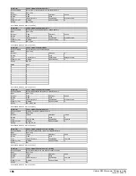
Parameter
14.002
PID1 Feed-forward Reference Source
Short description
Defines the input source for the feed-forwards reference source for PID1
Mode
Open
‑
loop
Minimum
0.000
Maximum
30.999
Default
0.000
Units
Type
16 Bit User Save
Update Rate
Drive reset read
Display Format
Standard
Decimal Places
3
Coding
RW, PT, BU
See
PID1 Output
(14.001) and
User PID Controller
(14).
Parameter
14.003
PID1 Reference Source
Short description
Defines the input source for the reference for PID1
Mode
Open
‑
loop
Minimum
0.000
Maximum
30.999
Default
0.000
Units
Type
16 Bit User Save
Update Rate
Drive reset read
Display Format
Standard
Decimal Places
3
Coding
RW, PT, BU
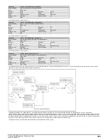
The reference section for the PID controller is shown in the introduction. The reference section is always active even if the PID controller itself is disabled or the reference source is not
routed to a valid parameter. If a reference source is not a valid parameter or is 0.000 then the value is taken as zero.
The reference is multiplied by
PID1 Reference Scaling
(14.023) and then limited to +/-100.00%. The reference can then be inverted if required (
PID1 Reference Invert
(14.005) = 1) and
then a slew rate limit is applied with
PID1 Reference Slew Rate
(14.007). This limits the maximum rate of change so that a change from 0.00 to 100.00% takes the time given in
PID1 Reference Slew Rate
(14.007).
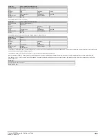
Parameter
14.004
PID1 Feedback Source
Short description
Defines the input source for the feedback for PID1
Mode
Open
‑
loop
Minimum
0.000
Maximum
30.999
Default
0.000
Units
Type
16 Bit User Save
Update Rate
Drive reset read
Display Format
Standard
Decimal Places
3
Coding
RW, PT, BU
The feedback section for the PID controller is shown in the introduction. The feedback section is always active even if the PID controller itself is disabled or the feedback source is not
routed to a valid parameter. If a reference source is not a valid parameter or is 0.000 then the value is taken as zero.
The feedback is the sum of the feedback source and the
PID1 Digital Feedback
(14.026). The result is multiplied by
PID1 Feedback Scaling
(14.024) and then limited to +/-100.00%.
The feedback can be inverted if required (
PID1 Feedback Invert
(14.006) = 1).
Unidrive M200 Parameter Reference Guide
Issue: 01.05.00.10
205
Summary of Contents for unidrive m200
Page 1: ...Parameter Reference Guide Unidrive M200 Open loop Mode Issue 01 05 00 10 ...
Page 30: ...30 Unidrive M200 Parameter Reference Guide Issue 01 05 00 10 ...
Page 83: ...Enable logic Unidrive M200 Parameter Reference Guide Issue 01 05 00 10 83 ...
Page 125: ...Unidrive M200 Parameter Reference Guide Issue 01 05 00 10 125 ...
Page 145: ...Unidrive M200 Parameter Reference Guide Issue 01 05 00 10 145 ...
Page 204: ...204 Unidrive M200 Parameter Reference Guide Issue 01 05 00 10 ...


