


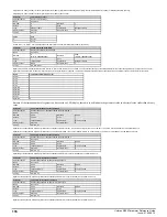


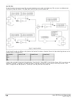
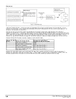
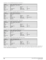
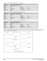
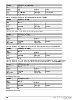
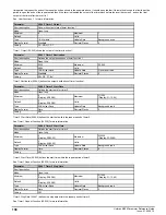

Logic functions
The logic functions are always active even if the sources and destinations are not routed to valid parameters. If the sources are not valid parameters
then the source values are taken as 0. The update rate for each of the logic functions is always 4ms
The logic function consists of an AND gate with inverters on each input and an inverter on the output. Some of the other standard logic functions can be
produced as shown in the table below.
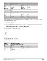
Logic function
Source 1 Invert
Source 2 Invert
Output Invert
AND
0
0
0
NAND
0
0
1
OR
1
1
1
NOR
1
1
0
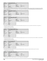
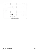
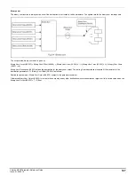
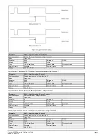
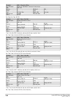
A delay function is provided at the output of the logic functions. If
Logic Function 1 Delay
(09.009) or
Logic Function 2 Delay
(09.019) is positive then the
output does not become 1 until the input to the delay has been at 1 for the delay time. If
Logic Function 1 Delay
(09.009) or
Logic Function 2 Delay
(09.019) is negative then the output remains at 1 until the input to the delay has been 0 for the delay time.
124
Unidrive M200 Parameter Reference Guide
Issue: 01.05.00.10
Summary of Contents for unidrive m200
Page 1: ...Parameter Reference Guide Unidrive M200 Open loop Mode Issue 01 05 00 10 ...
Page 30: ...30 Unidrive M200 Parameter Reference Guide Issue 01 05 00 10 ...
Page 83: ...Enable logic Unidrive M200 Parameter Reference Guide Issue 01 05 00 10 83 ...
Page 125: ...Unidrive M200 Parameter Reference Guide Issue 01 05 00 10 125 ...
Page 145: ...Unidrive M200 Parameter Reference Guide Issue 01 05 00 10 145 ...
Page 204: ...204 Unidrive M200 Parameter Reference Guide Issue 01 05 00 10 ...


