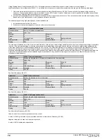

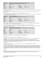


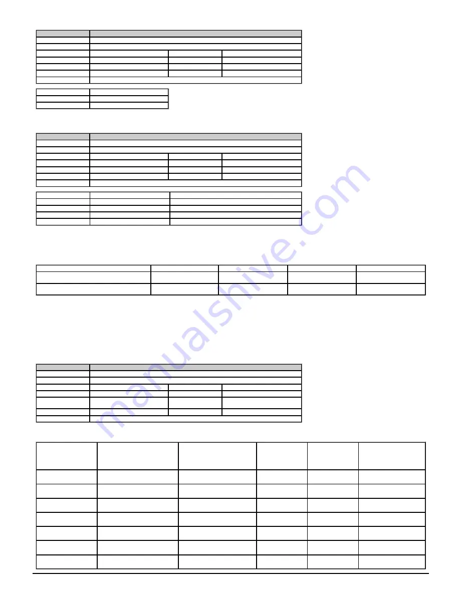
Parameter
06.002
Limit Switch Stop Mode
Short description
Defines the behaviour of the drive when limit switch is active
Mode
Open
‑
loop
Minimum
0
Maximum
1
Default
1
Units
Type
8 Bit User Save
Update Rate
Background read
Display Format
Standard
Decimal Places
0
Coding
RW, TE
Value
Text
0
Stop
1
rp
If
Limit Switch Stop Mode
(06.002) = 0 then when
Limit switch active
(10.066) is activated the motor is stopped without ramps (under dc injection control).
If
Limit Switch Stop Mode
(06.002) = 1 then the motor is stopped with the currently selected ramp rate.
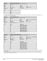
Parameter
06.003
Supply Loss Mode
Short description
Defines the behaviour of the drive when the supply voltage is reduced
Mode
Open
‑
loop
Minimum
0
Maximum
3
Default
0
Units
Type
8 Bit User Save
Update Rate
Background read
Display Format
Standard
Decimal Places
0
Coding
RW, TE
Value
Text
Description
0
diS
Disabled
1
rP.Stop
Ramp Stop
2
ridE.th
Ride through
3
Lt.Stop
Limit Stop
If
Supply Loss Mode
(06.003) > 0 and the
D.c. Link Voltage
(05.005) falls below
Supply Loss Detection Level
(06.048) then the supply loss condition is detected. If
Supply Loss Mode
(06.003) =
2 (ride through) the supply loss system will attempt to control the
D.c. Link Voltage
(05.005) to a level just below the
Supply Loss Detection Level
(06.048) using a d.c. link voltage controller
which provides a torque producing current reference to the current controllers to regulate the power flow into the d.c. link. Therefore
Current Controller Kp Gain
(04.013) and
Current Controller Ki Gain
(04.014) must be set up correctly for the application. When the supply is reapplied it must be at a level that is high enough for the
D.c. Link Voltage
(05.005) to rise
above
Supply Loss Detection Level
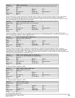
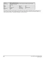
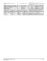
(06.048) plus a hysteresis margin. This will disable the supply loss controller and the drive will return to normal operation. The table below gives the d.c. link
voltage levels used by the supply loss detection system for different drive voltage ratings.
Voltage level
200V
400V
575V
690V
Supply loss d.c. link voltage control level
Supply Loss Detection Level
(06.048) - 10V
Supply Loss Detection Level
(06.048) - 20V
Supply Loss Detection Level
(06.048) - 25V
Supply Loss Detection Level
(06.048) - 25V
Voltage above which supply loss detection changes
from active to inactive
Supply Loss Detection Level
(06.048) +10V
Supply Loss Detection Level
(06.048) + 15V
Supply Loss Detection Level
(06.048) + 50V
Supply Loss Detection Level
(06.048) + 50V
0: Disable
No supply loss detection is provided by monitoring the
D.c. Link Voltage
(05.005). The drive will continue to operate normally unless the under voltage condition is detected.
1: Ramp Stop
The action taken by the drive is the same as for ride through mode, except that the ramp down rate is at least as fast as the currently selected deceleration ramp and the drive will continue to
decelerate and stop even if the supply is re-applied. If
Stop Mode
(06.001) = 3 or 4 (i.e. d.c. injection) the drive will use ramp mode to stop on loss of the supply. If
Stop Mode
(06.001) = 2 (i.e.
ramp stop followed by injection) the drive will ramp to a stop and then attempt to apply d.c. injection. The ramp down rate is at least as fast as the currently selected deceleration ramp and the
drive will continue to decelerate and stop even if the supply is re-applied. Once the sequencer state machine has reached the DISABLE state the drive can restart provided the necessary
controls are still active to initiate a start.
2: Ride through
The drive attempts to control the d.c. link voltage to take energy from the motor and load inertia to ride through the Supply loss condition for as long as possible.
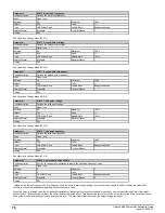
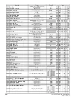
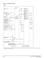
Parameter
06.004
Start/Stop Logic Select
Short description
Used to select the logic function of the drive input terminals
Mode
Open
‑
loop
Minimum
0
Maximum
6
Default
0
Units
Type
8 Bit User Save
Update Rate
Actioned on exit of edit mode and on
drive reset
Display Format
Standard
Decimal Places
0
Coding
RW
This parameter changes the functions of the input terminals which are normally associated with the enabling, starting and stopping the drive. This also writes to
Enable Sequencer Latching
(06.040) to enable and disable the input latches.
Start/Stop Logic Select
(06.004)
Digital I/O 2 (M100 - M201)
Terminal 11
Digital I/O 2 (M300- M400)
Terminal 11
Digital Input 3
Terminal 12
Digital Input 4
Terminal 13
Enable Sequencer Latching
(06.040)
0 (default)
User Enable
Undefined
Run Forward
Run Reverse
0 (non-latching)
1
Not Stop
Not Stop
Run Forward
Run Reverse
1 (latching)
2
User Enable
Undefined
Run
Reverse
0 (non-latching)
3
Not Stop
Not Stop
Run
Reverse
1 (latching)
4
Not Stop
Not Stop
Run
Jog Forward
1 (latching)
5
User programmable
User programmable
Run Forward
Run Reverse
0 (non-latching)
6
User programmable
User programmable
User programmable
User programmable
User programmable
86
Unidrive M200 Parameter Reference Guide
Issue: 01.05.00.10
Summary of Contents for unidrive m200
Page 1: ...Parameter Reference Guide Unidrive M200 Open loop Mode Issue 01 05 00 10 ...
Page 30: ...30 Unidrive M200 Parameter Reference Guide Issue 01 05 00 10 ...
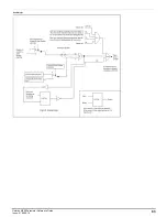
Page 83: ...Enable logic Unidrive M200 Parameter Reference Guide Issue 01 05 00 10 83 ...
Page 125: ...Unidrive M200 Parameter Reference Guide Issue 01 05 00 10 125 ...
Page 145: ...Unidrive M200 Parameter Reference Guide Issue 01 05 00 10 145 ...
Page 204: ...204 Unidrive M200 Parameter Reference Guide Issue 01 05 00 10 ...


