


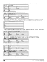


Parameter
07.028
Analog Input 1 Current Loop Loss
Short description
Displays when analog input 1 falls below 3mA
Mode
Open
‑
loop
Minimum
0
Maximum
1
Default
Units
Type
1 Bit Volatile
Update Rate
Background write
Display Format
Standard
Decimal Places
0
Coding
RO, ND, NC, PT
See
Analog Input 1 Preset on Current Loss
(07.026).
Parameter
07.030
Analog Input 1 Offset
Short description
Defines the offset of analog input 1
Mode
Open
‑
loop
Minimum
-100.00
Maximum
100.00
Default
0.00
Units
%
Type
16 Bit User Save
Update Rate
Background read
Display Format
Standard
Decimal Places
2
Coding
RW
See
Analog Input 1 Scaling
(07.008).
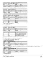
Parameter
07.031
Analog Input 2 Offset
Short description
Defines the offset of analog input 2
Mode
Open
‑
loop
Minimum
-100.00
Maximum
100.00
Default
0.00
Units
%
Type
16 Bit User Save
Update Rate
Background read
Display Format
Standard
Decimal Places
2
Coding
RW
See
Analog Input 2 Scaling
(07.012).
Parameter
07.034
Inverter Temperature
Short description
Displays the estimated junction temperature of the hottest power device within the drive inverter
Mode
Open
‑
loop
Minimum
-250
Maximum
250
Default
Units
°C
Type
16 Bit Volatile
Update Rate
Background write
Display Format
Standard
Decimal Places
0
Coding
RO, ND, NC, PT
Inverter Temperature
(07.034) shows the estimated junction temperature of the hottest power device within the drive inverter. If this temperature exceeds the switch down threshold defined for the
power stage the switching frequency is reduced provided this feature has not been disabled (i.e.
Auto-switching Frequency Change Disable
(05.035) = 0) or the minimum switching frequency has
not been reached. The switching frequency can be reduced from 12kHz to 6kHz to 3kHz, or from 16kHz to 8kHz to 4kHz to 2kHz. If the switching frequency has been reduced the drive will
attempt to restore it to the required level when the
Inverter Temperature
(07.034) reduces.
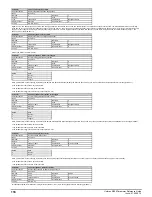
Parameter
07.035
Percentage Of d.c. Link Thermal Trip Level
Short description
Displays the percentage of the maximum allowed temperature as estimated by the thermal model of the
d.c. link components
Mode
Open
‑
loop
Minimum
0
Maximum
100
Default
Units
%
Type
8 Bit Volatile
Update Rate
Background write
Display Format
Standard
Decimal Places
0
Coding
RO, ND, NC, PT
Percentage Of d.c. Link Thermal Trip Level
(07.035) gives the percentage of the maximum allowed temperature as estimated by the thermal model of the d.c. link components.
Parameter
07.036
Percentage Of Drive Thermal Trip Level
Short description
Displays the percentage of the thermal trip level of the temperature monitoring point or thermal model in
the drive that is highest
Mode
Open
‑
loop
Minimum
0
Maximum
100
Default
Units
%
Type
8 Bit Volatile
Update Rate
Background write
Display Format
Standard
Decimal Places
0
Coding
RO, ND, NC, PT
Percentage Of Drive Thermal Trip Level
(07.036) gives the percentage of the thermal trip level of the temperature monitoring point or thermal model in the drive that is highest. This includes all
thermal monitoring points
Stack Temperature
(07.004),
Auxiliary Temperature
(07.005),
Inverter Temperature
(07.034) and
Percentage Of d.c. Link Thermal Trip Level
(07.035).
Percentage Of d.c. Link Thermal Trip Level
(07.035) is used directly to give
Percentage Of Drive Thermal Trip Level
(07.036), but for all other monitored values which are temperatures this is
given by
Percentage of thermal trip level = (Measured Temperature - 40°C) / (Trip temperature - 40°C) x 100%
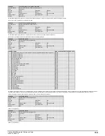
The location of the measurement or the thermal model that is related to this temperature is given in
Temperature Nearest To Trip Level
(07.037). If
Percentage Of Drive Thermal Trip Level
(07.036) exceeds 90%
Drive Over-temperature Alarm
(10.018) is set to one. If
Percentage Of Drive Thermal Trip Level
(07.036) reaches 100% one of the trips given in the table below is initiated.
The trip can be reset when the percentage of thermal trip level falls below 95%.
Temperature
Trip
Inverter Temperature
(07.034)
OHt Inverter
Stack Temperature
(07.004) and
Auxiliary Temperature
(07.005)
OHt Power
Percentage Of d.c. Link Thermal Trip Level
(07.035)
OHt dc bus
Unidrive M200 Parameter Reference Guide
Issue: 01.05.00.10
105
Summary of Contents for unidrive m200
Page 1: ...Parameter Reference Guide Unidrive M200 Open loop Mode Issue 01 05 00 10 ...
Page 30: ...30 Unidrive M200 Parameter Reference Guide Issue 01 05 00 10 ...
Page 83: ...Enable logic Unidrive M200 Parameter Reference Guide Issue 01 05 00 10 83 ...
Page 125: ...Unidrive M200 Parameter Reference Guide Issue 01 05 00 10 125 ...
Page 145: ...Unidrive M200 Parameter Reference Guide Issue 01 05 00 10 145 ...
Page 204: ...204 Unidrive M200 Parameter Reference Guide Issue 01 05 00 10 ...


