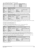
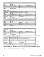
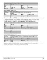
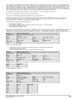

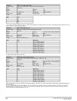
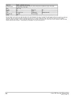

Parameter
Required for
Measured in test
Motor Rated Frequency
(05.006)
Basic control
Motor Rated Current
(05.007)
Basic control
Motor Rated Speed
(05.008)
Slip compensation
Catch a spinning motor
Motor Rated Voltage
(05.009)
Basic control
Motor Rated Power Factor
(05.010)
Basic control
2
Number Of Motor Poles
(05.011)
Basic control
Stator Resistance
(05.017)
Ur, Ur I, Ur S and Ur Auto modes
Catch a spinning motor
1, 2
Transient Inductance
(05.024)
Improved performance
1, 2
Stator Inductance
(05.025)
Improved performance
2
Maximum Deadtime Compensation
(05.059)
Basic control
1, 2
Current At Maximum Deadtime Compensation
(05.060)
Basic control
1, 2
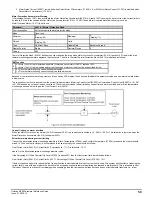
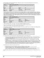
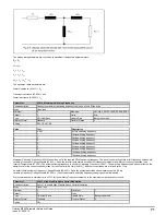
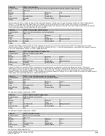
Auto-tune test 1: Basic control parameters
This test measures the basic control parameters without moving the motor.
1. A stationary test is performed to measure
Stator Resistance
(05.017),
Transient Inductance
(05.024),
Maximum Deadtime Compensation
(05.059) and
Current At Maximum Deadtime Compensation
(05.060).
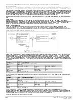
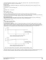
Auto-tune test 2: Basic control and improved performance parameters
This test measures the parameters for improved performance by rotating the motor.
1. Auto-tune test 1 is performed.
2. A rotating test is performed in which the motor is accelerated with the currently selected ramps up to a frequency of
Motor Rated Frequency
(05.006)
x 2/3, and the frequency is maintained at that level for 4 seconds.
Stator Inductance
(05.025) is measured and this value is used in conjunction with
other motor parameters to calculate
Motor Rated Power Factor
(05.010). The motor should be unloaded for this test.
The table below shows the trips that can occur during an auto-tune test:
Trip
Reason
Trip can occure in
test
Autotune Stopped
The final drive enable or the final drive run were removed before the test
was completed.
All
Resistance
The measured value of
Stator Resistance
(05.017) exceeded the range of
the parameter.
All
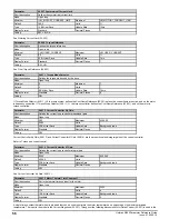
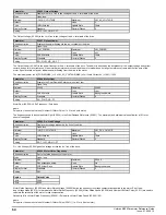
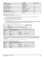
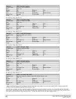
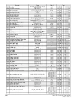
Parameter
05.013
Dynamic V To F Select
Short description
Set to 1 to enable Dynamic V to F mode
Mode
Open
‑
loop
Minimum
0
Maximum
1
Default
0
Units
Type
8 Bit User Save
Update Rate
Background read
Display Format
Standard
Decimal Places
0
Coding
RW
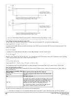
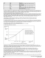
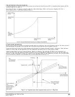
Dynamic V to F mode is intended for applications where power loss should be kept to a minimum under low load conditions, but dynamic performance is not
important. The reduction in power loss under low load conditions is achieved by increasing the rated frequency used to derive the frequency to voltage
characteristic of the drive with reduced load. If
Flux Optimisation Select, Dynamic V To F Select
(05.013) = 0 then
Motor Rated Frequency
(05.006) is used
directly to define the output voltage characteristic. If
Flux Optimisation Select, Dynamic V To F Select
(05.013) = 1 then a modified value of motor rated
frequency is used:
Motor rated frequency =
Motor Rated Frequency
(05.006) x [2 - |
Percentage Load
(04.020)| / 70.0%]
For loads > 70%
Motor Rated Frequency
(05.006) is used directly.
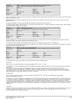
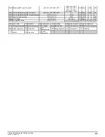
Parameter
05.014
Open-loop Voltage Mode
Short description
Defines the mode used to set the output voltage
Mode
Open
‑
loop
Minimum
0
Maximum
6
Default
4
Units
Type
8 Bit User Save
Update Rate
Background read
Display Format
Standard
Decimal Places
0
Coding
RW, TE
Unidrive M200 Parameter Reference Guide
Issue: 01.05.00.10
67
Summary of Contents for unidrive m200
Page 1: ...Parameter Reference Guide Unidrive M200 Open loop Mode Issue 01 05 00 10 ...
Page 30: ...30 Unidrive M200 Parameter Reference Guide Issue 01 05 00 10 ...
Page 83: ...Enable logic Unidrive M200 Parameter Reference Guide Issue 01 05 00 10 83 ...
Page 125: ...Unidrive M200 Parameter Reference Guide Issue 01 05 00 10 125 ...
Page 145: ...Unidrive M200 Parameter Reference Guide Issue 01 05 00 10 145 ...
Page 204: ...204 Unidrive M200 Parameter Reference Guide Issue 01 05 00 10 ...


