


ROC364 Instruction Manual
2-3
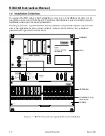
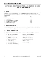
Master Controller Unit, I/O Module Rack, and Wiring
Rev Jun/05
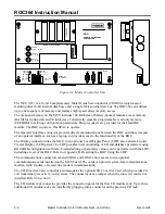
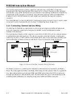
Power fusing is accessible from the front of the MCU. Fuses are used for the input power and auxiliary
power outputs. Terminal blocks provide terminations for the input and auxiliary output power. The
source of auxiliary power is the input power, which can be a nominal 12 or 24 volts, depending on the
setting of jumpers located on the MCU. Refer to Section 2.3.3, Setting Voltage Jumpers in the MCU, on
page 2-8.
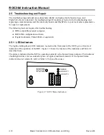
Indicators are provided for System Status, ROC Power, and auxiliary power (AUX OUT 1 and AUX
OUT 2). Refer to Section 2.5.1, LED Indicators, on page 2-12.
The MCU is housed in a metal case that protects the electronics from physical damage. For protection
from outdoor environments, the unit must be housed in an approved enclosure.
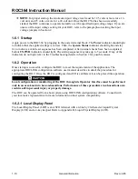
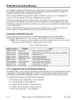
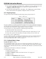
2.2.2 FlashPAC Module
The FlashPAC module contains the operating system, the applications firmware, and communications
protocol, as well as memory storage for history logs and user programs. A FlashPAC module contains
512 kilobytes of flash read-only memory (ROM) and 512 kilobytes of battery-backed Static Random
Access Memory (SRAM). A FlashPAC module is required for the ROC to operate. Back-up power for
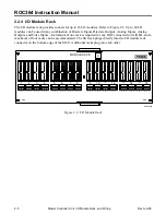
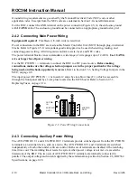
the RAM is provided by a self-contained lithium battery. Figure 2-2 shows a FlashPAC module.
The applications firmware consists of functions contained in flash ROM such as:
♦
AGA3 (1985 and 1992 algorithms) and AGA7 Flow Calculations, with metric conversion.
♦
PID (Proportional, Integral, and Derivative) Loop Control.
♦
Support for Function Sequence Tables (FSTs).
♦
Communications Enhancement (dial-up Spontaneous-Report-by-Exception (SRBX) alarming).
♦
Local Display Panel Enhancement (database point monitoring along with configuration access).
♦
Radio Power Control (FlashPAC Version 2.1 or greater).
ROC300 SERIES
VER: 2.10
PATENT 5339425
FLASHPAC
®
DOC0292A
-------------
W20217X0012
Figure 2-2. Typical FlashPAC Module


