


ROC364 Instruction Manual
2-10
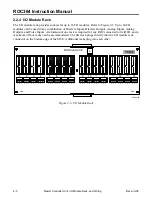
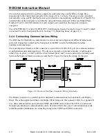
Master Controller Unit, I/O Module Rack, and Wiring
Rev Jun/05
Ground wiring requirements are governed by the National Electrical Code (NEC) code or other
applicable codes. Excerpts from the NEC code are contained in Section 1, General Information.
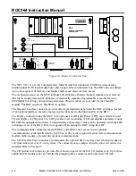
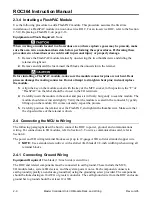
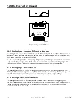
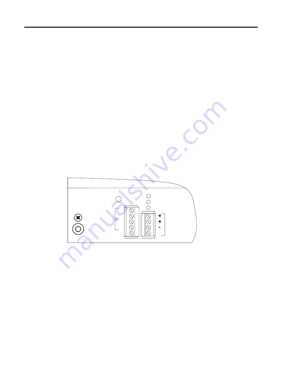
For the ROC, connect the GND terminal on the power connector (Figure 2-5) to the enclosure ground
with
12 AWG wire
. The enclosure ground must be connected to an appropriate ground rod or grid.
2.4.2 Connecting Main Power Wiring
Equipment Required:
Flat-blade (1/8-inch wide) screwdriver
Power connections to the ROC are made at the Master Controller Unit (MCU) through plug-in terminal
blocks. Refer to Figure 2-5. It is important good wiring practice be used when sizing, routing, and
connecting power wiring. All wiring must conform to state, local, and NEC codes.
The power terminal blocks can accommodate a wide range of wire gauges up to 12 AWG.
Use 18 AWG
wire or larger for all power wiring.
Use the DC PWR IN +/– terminals to connect the ROC to a DC power source.
Before making
connections, make sure the voltage selection jumpers are in the proper position for the voltage
being used, and the hook-up polarity is correct.
Refer to Section 2.3.3, Setting Voltage Jumpers in the
MCU, on page 2-8.
The input power (DC PWR IN +/–) is fused at 2 amps by slow-blow fuse (F1), which is accessible
through the front panel and by a 3-amp fuse located on the MCU board. Refer to Section 2.5.3,
Replacing Fuses, on page 2-14.
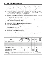
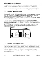
DOC0123A
-
AUX PWR
OUT 2
+
-
-
+
DC PWR
IN
AUX PWR
OUT 1
GND
Figure 2-5. Power Wiring Connections
2.4.3 Connecting Auxiliary Power Wiring
The AUX PWR OUT 1 and AUX PWR OUT 2 terminals provide switched power from the DC PWR IN
terminals to an external device, such as a radio. The AUX PWR OUT 1 and 2 terminals are switched
independently of each other under software control. Both sets of terminals are disabled if the watchdog
timer times out. The watchdog timer resets the system when power voltage is not met or exceeds the
limitations of the ROC. The two sets of AUX PWR OUT 2 terminals are internally connected in
parallel. The output voltage and current supplied by these terminals is specified in Section 2.6, ROC364
Specifications, on page 2-20.


