


ROC364 Instruction Manual
2-7
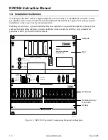
Master Controller Unit, I/O Module Rack, and Wiring
Rev Jun/05
2.3 Installation
Component installation is normally performed at the factory when the ROC is ordered. However, the
modular design of the ROC makes it easy to install and to change hardware configurations in the field as
required. The following procedures describe installation of a ROC.
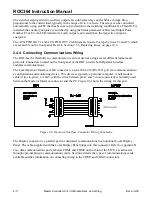
If you are installing the ROC364 into a ROC enclosure, fasten the backplate to the mounting studs or
tapped mounting holes provided in the enclosure. If you installing the ROC364 on a wall panel or in
some other enclosure, refer to Figure 2-4 for the recommended size and location of mounting studs.
For ROC364 units that are currently in service, you must take certain precautions to ensure data is not
lost, equipment is not damaged, and personnel are not exposed to electrical hazards. Refer to Section
2.5, Troubleshooting and Repair, on page 2-12.
When installing units in a hazardous area, ensure that the components selected are labeled for use
in such areas. Change components only in an area known to be non-hazardous. Performing these
procedures in a hazardous area could result in personal injury or property damage.
To add I/O modules, refer to Section 3. To add a communications card, refer to Section 4. To install
accessories for use with the ROC, refer to the
ROC/ROC Accessories Instruction Manual
(Form A4637).
2.3.1 Mounting the Master Controller Unit to a Backplate
The Master Controller Unit (MCU) and I/O module rack(s) mount to a factory-supplied backplate,
which can be mounted inside an enclosure. The backplates are pre-drilled and tapped to accept the MCU
and one to four I/O module racks. Refer to Figure 2-4.
Equipment and Tools Required:
Flat-blade (1/8-inch wide) screwdriver
To mount the MCU to a backplate:
1.
Make sure the proper size backplate is being used for the number of I/O module racks
to be installed.
2.
Locate the alignment screws on the backplate and place the keyhole slots, located on the base of
the MCU, over the screw heads.
3.
Slide the MCU over the alignment screws and secure in place with two 8-32
×
1 inch and
two 8-32
×
2.25 inch screws.


