ROC364 Instruction Manual
1-10
General Information
Rev Jun/05
NOTE:
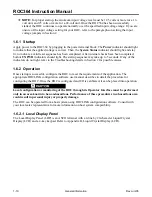
For proper startup, the minimum input voltage level must be 12.5 volts or more for a 12-
volt unit, and 25 volts or more for a 24-volt unit. Once the ROC364 has been successfully
started, the ROC continues to operate normally over the specified input voltage range. If you are
unsure of the input voltage setting for your ROC, refer to the paragraphs on setting the input
voltage jumpers in Section 2.
1.6.1 Startup
Apply power to the ROC364 by plugging in the power terminal block. The
Power
indicator should light
to indicate that the applied voltage is correct. Then, the
System Status
indicator should light, and stay
lit, to indicate a valid reset sequence has been completed. After internal checks have been completed,
both
AUX PWR
indicators should light. The startup sequence may take up to 5 seconds. If any of the
indicators do not light, refer to the Troubleshooting details in Section 2 for possible causes.
1.6.2 Operation
Once startup is successful, configure the ROC to meet the requirements of the application. The
appropriate ROCLINK configuration software user manual
describes in detail the procedure for
configuring the ROC. Once the ROC is configured and I/O is calibrated, it can be placed into operation.
Local configuration or monitoring of the ROC through its Operator Interface must be performed
only in an area known to be non-hazardous. Performance of these procedures in a hazardous area
could result in personal injury or property damage.
The ROC can be operated from a host system using ROCLINK configuration software. Consult with
your local sales representative for more information on host system compatibility.
1.6.2.1 Local Display Panel
The Local Display Panel (LDP) is an ASCII terminal with a 4-line by 20-character Liquid Crystal
Display (LCD) and a 4-key keypad. Refer to Appendix B, Liquid Crystal Display (LCD).


