ROC364 Instruction Manual
2-2
Master Controller Unit, I/O Module Rack, and Wiring
Rev Jun/05
DOC0119A
F
L
A
S
H
P
A
C
SYSTEM
STATUS
GND
AUX PWR
OUT 1
DC PWR
IN
+
-
-
+
AUX PWR
OUT 2
AUX OUT 2
AUX OUT 1
-
-
+
+
POWER
OPERATOR
INTERFACE
COM2
COM1
DISPLAY
ROC
REMOTE OPERATIONS
CONTROLLER
RAM
MEMORY EXPANSION
3
2
1
F3
F2
F1
AUX OUT 2
5A, 32 VDC
5A, 32 VDC
AUX OUT 1
POWER
2A S.B., 32 VDC
®
F
L
A
S
H
P
A
C
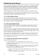
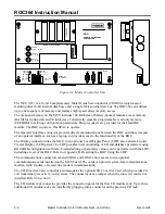
Figure 2-1. Master Controller Unit
The NEC V25+ is a 16-bit Complementary Metal Oxide Semiconductor (CMOS) microprocessor
featuring dual 16-bit internal data buses and a single 8-bit external data bus. The ROC364 can address
up to one megabyte of memory and features high-speed direct memory access.
The on-board memory on the MCU includes 128 kilobytes of battery-backed, random access memory
(RAM) for storing data and 32 kilobytes of electrically erasable programmable read only memory
(EEPROM) for storing configuration parameters. Plug-in sockets are provided for the FlashPAC
module. The ROC requires a FlashPAC to operate.
The Operator Interface connector provides direct communications between the ROC and the serial port
of an operator interface, such as a laptop, to provide access to the functionality of the ROC.
The Display connector links the MCU to an optional Local Display Panel (LDP), also called a Liquid
Crystal Display (LCD) panel. The LDP provides local monitoring of I/O and database parameters using
ROCLINK configuration software. Limited editing of parameter values can be performed with the LDP,
including a reset of the ROC. Refer to Appendix B, Resetting the ROC Using the LDP.
The communications connectors labeled COM1 and COM2 allow access to two optional
communications cards installed on the MCU board. The cards can provide serial data communications,
modem, radio modem, or leased-line modem communications.
The I/O Converter Card connector accommodates the optional I/O Converter Card, which provides 24-
volt transmitter power in 12-volt systems. The connector uses a jumper when the converter card is not
installed. Refer to Section 5.
The I/O module rack connector provides the connection point for the first I/O module rack. Up to three
additional I/O module racks are installed by plugging into a connector on the previous I/O rack.

