


ROC364 Instruction Manual
3-5
Input and Output Modules
Rev Jun/05
3.3 Initial Installation and Setup
Each I/O module installs in the ROC in the same manner. Any I/O module can be installed into any I/O
module socket. To install a module on a ROC that is not in service, perform the following steps. For an
in-service ROC, refer to Section 3.5, Troubleshooting and Repair, on page 3-21.
Failure to exercise proper electrostatic discharge precautions (such as wearing a grounded wrist
strap) may reset the processor or damage electronic components, resulting in interrupted
operations.
When preparing a unit for installation into a hazardous area, change components in an area
known to be non-hazardous.
1.
Install the I/O module by aligning the pins with the desired I/O module socket and pressing
gently, but straight down.
2.
Tighten the module retaining screw.
3.
Make sure a field wiring terminal block is installed in the socket adjacent to where the I/O
module was installed. If a Lightning Protection Module is to be installed for this I/O channel,
refer to Appendix A.
3.3.1 Calibrating an I/O Module
After an I/O module is installed, configure, and calibrate the associated I/O channel using ROCLINK
configuration software.
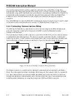
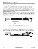
3.4 Connecting the I/O Modules to Wiring
Each I/O module electrically connects to field wiring by a separate plug-in terminal block. In addition,
the ROC enclosures provide a ground bus bar for terminating the sheath on shielded wiring. The
following paragraphs provide information on wiring field devices to each type of I/O module. I/O wiring
terminal blocks accept up to 12-gauge AWG solid or stranded copper wire.
The sheath surrounding shielded wiring should never be connected to a signal ground terminal or
to the common terminal of an I/O module. Doing so makes the I/O module susceptible to static
discharge, which can permanently damage the module. Connect the shielded wiring sheath to a
suitable earth ground only.


