


ROC364 Instruction Manual
3-14
Input and Output Modules
Rev Jun/05
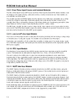
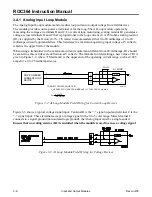
A 10-ohms scaling resistor (R1) is supplied by the factory and accommodates a source voltage (V
s
) of
11 to 30 volts dc and a pulse source with a 50% Duty Cycle. The source voltage is the input voltage to
the ROC. However, it is desirable to optimize the value of R1 to reduce the current drain from the
source or reduce the heat generated in the module due to high source voltage. The formula for
determining the value of R1 is given in Figure 3-16. For optimum efficiency, R1 should be scaled for a
loop current (I) of 5 milliamps.
PULSE DEVICE
ROC-POWERED
V
S
= SOURCE VOLTAGE FROM MODULE = 11 TO 30 VDC
R1 + R
W
+ 2.2K = LOOP RESISTANCE = 3.4K OHMS MAX
– R
W
– 2.2K
R
W
= RESISTANCE OF FIELD WIRING
TO OPTIMIZE SCALING RESISTOR R1:
I = LOOP CURRENT = 5 mA TYPICAL
R1 =
I
I
R
W
V
S
– 1
B
C
–
A
N/C
+
R1=10
2.2K
PI SRC
V
S
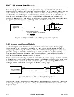
Figure 3-16. Pulse Input Source Module Field Wiring
3.4.11 Pulse Input Isolated Module
A schematic representation of the field wiring connections to the input circuit of the Pulse Input Isolated
module is shown in Figure 3-17.
NOTE:
The Pulse Input Isolated module is designed to operate only with devices having their
own power source, such as “wet” relay contacts or two-state devices providing an output voltage.
The module is inoperative with non-powered devices.
The Pulse Input Isolated module operates when a field device provides a voltage across terminals B and
C of the module. The voltage sets up a flow of current sensed by the module. When the field device no
longer provides a voltage, current stops flowing.
This interrupted, or pulsed current flow is counted and accumulated by the PI module, which provides
the accumulated count to the ROC electronics upon request.
A 10-ohms scaling resistor (R1) is supplied by the factory, which accommodates a field device with
pulse amplitude (V
o
) of 11 to 30 volts dc and a Duty Cycle of 50%. However, it is desirable to optimize
the value of R1 to reduce the current drain from the source or reduce the heat generated in the module
due to amplitudes greater than 30 volts dc. The formula for determining the value of R1 displays in
Figure 3-17. For optimum efficiency, R1 should be scaled for a loop current (I) of 5 milliamps.


