ROC364 Instruction Manual
B-13
Local Display Panel
Rev Jun/05
B.3.5.3 SYS Parameter Display 3
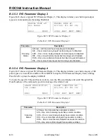
Figure B-18 shows a typical SYS Parameter Display 3. This display informs you which input/output
types are in manual mode (Scanning Disabled).
MANUAL MODE AT:
MANUAL MODE AT:
ALL CLEAR
AIS AOS DIS DOS PIS
HOLD
MENU
SCAN PREV
NEXT
MENU
Figure B-18. SYS Parameter Display 3
Table B-11. SYS Parameter Display 3
Parameter Description
Scanning
States
All Clear – All I/O points have Scanning set to Enabled.
AIS – One or more Analog Inputs has Scanning set to Disabled.
AOS – One or more Analog Outputs has Scanning set to Disabled.
DIS – One or more Discrete Inputs has Scanning set to Disabled.
DOS – One or more Discrete Outputs has Scanning set to Disabled.
PIS – One or more Pulse Inputs has Scanning set to Disabled.
B.3.5.4 SYS Parameter Display 4
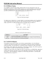
Figure B-19 shows a typical SYS Parameter Display 4. This display informs you which category of I/O
point types are in an alarm condition. Press HOLD to stop the SYS Parameter Display from scrolling.
Press SCAN to place the display in HOLD.
To locate the specific I/O point that is in alarm, view the I/O point display and scroll through all the
Point Numbers of the indicated type while looking at the Alarm Code.
ALARM CONDITION AT:
ALARM CONDITION AT:
ALL CLEAR
AIS AOS DIS DOS PIS
HOLD
MENU
SCAN
PREV
NEXT
MENU
Figure B-19. SYS Parameter Display 4
Table B-12. SYS Parameter Display 4
Parameter Description
Scanning
States
All Clear – No I/O points have an alarm condition.
AIS – One or more Analog Inputs has an alarm condition.
AOS – One or more Analog Outputs has an alarm condition.
DIS – One or more Discrete Inputs has an alarm condition.
DOS – One or more Discrete Outputs has an alarm condition.
PIS – One or more Pulse Inputs has an alarm condition.


