


ROC364 Instruction Manual
3-9
Input and Output Modules
Rev Jun/05
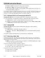
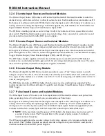
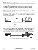
For example, a 250-ohms scaling resistor would accommodate either 0 to 20 milliamps, or 4 to 20
milliamps current loop transmitters (the transmitter must be able to operate on 10 volts dc or be powered
from another source). This translates to a maximum operating input voltage of 5 volts dc, which is the
upper limit of the module. When using a transmitter with a maximum operating current requirement
different from 20 milliamps, R1 should be sized to achieve full-scale deflection at 5 volts. The formula
for determining a new value of R1 displays in Figure 3-8.
I
CURRENT LOOP
DEVICE
ROC-POWERED
TO SELECT PROPER VALUE OF R1:
Vs = SOURCE VOLTAGE FROM MODULE = 10 Vdc, 20 mA MAX
–
+
+10 Vdc
B
I MAXIMUM
R1 =
5 VOLTS
C
–
A
+
R1
V SRC
AI SRC
Vs
Figure 3-8. AI Source Module Field Wiring for Current Loop Devices
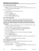
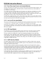
3.4.4 Analog Output Source Module
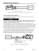
A schematic representation of the field wiring connections to the output circuit of the Analog Output
Source module displays in Figure 3-9 and Figure 3-10. The AO Source module can provide either loop
current or output voltage to non-powered field devices. The Analog Output Source module provides a 0
to 5.5 volts output at terminal A, and a 0 to 30 milliamps current source output at terminal B. Terminal
C is referenced to the ROC common.
Resistor R1 (0-ohm resistor supplied) helps keep the loop resistance within the operating range of the
module.
Remove the 0-ohm resistor when the loop resistance between terminals B and C is less
than 100 ohms
.
Terminals A and B are both active at the same time. Figure 3-9 shows wiring for a ROC-powered
current loop device, and Figure 3-10 shows wiring for an output voltage to non-powered field devices.
R1=0
DOC0158A
(Modified)
LEVEL
220
AO SRC
I
REMOVE RESISTOR R1 WHEN LOOP
RESISTANCE IS LESS THAN 100 OHMS
I = 30 mA MAX
COM
+I
-
C
B
+
+V
A
ROC-POWERED
LOOP DEVICE
Figure 3-9. Analog Output Source Module Field Wiring for Current Loop Devices


