ROC364 Instruction Manual
1-3
General Information
Rev Jun/05
1.4 Installation Guidelines
The design of the ROC makes it highly adaptable to a wide variety of installations; therefore, not all
possibilities can be covered in this manual. If additional information is required concerning a specific
installation, contact your local sales representative.
Planning is essential to a good installation. Because installation requirements depend on many factors
such as the application, location, ground conditions, climate, and accessibility, only generalized
guidelines can be provided in this document.
ROC364
SYSTEM
STATUS
GND
AUX PWR
OUT 1
DC PWR
IN
+
-
-
+
AUX PWR
OUT 2
AUX OUT 2
AUX OUT 1
-
-
+
+
POWER
OPERATOR
INTERFACE
COM2
COM1
DISPLAY
ROC
REMOTE OPERATIONS
CONTROLLER
RAM
MEMORY EXPANSION
3
2
1
F3
F2
F1
AUX OUT 2
5A, 32 VDC
5A, 32 VDC
AUX OUT 1
POWER
2A S.B., 32 VDC
®
F
L
A
S
H
P
A
C
1
2
3
4
8
7
6
5
9
14
15
16
13
12
11
10
A
B C
C
B
A
C
B
A
C
B
A
C
B
A
C
B
A
C
B
A
C
B
A
A
B C
A
B
C
A
B C
A
B C
C
B
A
C
B
A
C
B
A
C
B
A
GND
GND
®
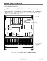
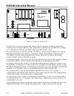
Figure 1-1. ROC364 Controller Components Mounted on Backplate
MCU
I/O Modules
I/O Module Wiring /
Termination
I/O Rack
Backplate


