


ROC364 Instruction Manual
2-1
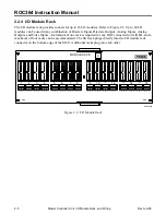
Master Controller Unit, I/O Module Rack, and Wiring
Rev Jun/05
SECTION 2 – MASTER CONTROLLER UNIT, I/O MODULE
RACK, AND WIRING
2.1 Scope
This section describes the core of the ROC364 components, including the Master Controller Unit
(MCU), the FlashPAC module, wiring, the I/O Module rack, the backplate, and the front panel. Topics
covered include:
Section Page
2.2 Product
Description
2-1
2.3 Installation
2-7
2.4
Connecting the MCU to Wiring
2-9
2.5
Troubleshooting and Repair
2-12
2.6 ROC364
Specifications
2-20
2.2 Product Description
The following subsections describe components of the ROC364 including the Master Controller Unit,
FlashPACs, Diagnostic Analog Inputs, Auxiliary Discrete Outputs, I/O Module Rack, and Backplate.
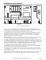
2.2.1 Master Controller Unit
The Master Controller Unit (MCU) is the “brain” of the ROC. Figure 2-1 displays MCU. The MCU
consists of:
♦
NEC V25+ microprocessor.
♦
I/O converter card connector.
♦
On-board memory.
♦
I/O module rack connector.
♦
FlashPAC module sockets.
♦
Diagnostic Analog Inputs.
♦
Operator Interface port.
♦
Auxiliary Discrete Outputs.
♦
Local Display port.
♦
Status indicators.
♦
Communications ports.
♦
Metal housing.
♦
Power fusing and terminations.


