ROC364 Instruction Manual
A-1
Lightning Protection Module
Rev Jun/05
APPENDIX A – LIGHTNING PROTECTION MODULE
This appendix describes the Lightning Protection Module (LPM) used with the Remote Operations
Controller.
This section contains the following information:
Section Page
A.1 Product
Description
A-1
A.2 Connecting the LPM to Wiring
A-2
A.3 Troubleshooting and Repair
A-2
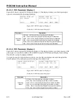
A.4 Lightning Protection Module Specifications
A-3
A.1 Product Description
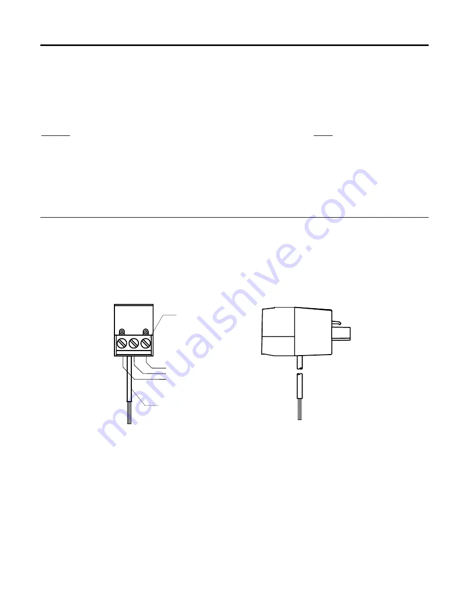
Figure A-1 shows a front and side view of the module. The LPM helps prevent damage to I/O modules
and to built-in I/O circuitry from any high-voltage transients that may occur in field wiring. The LPMs
plug into the field wiring I/O module sockets.
The LPM provides screw terminals for connecting to field wiring. It has sockets for plugging in a range
resistor, especially when used with built-in I/O. The module also provides a ground wire for connection
to the enclosure ground bar.
}
LPM-2
FRONT VIEW
BUILT-IN FIELD WIRING
TERMINATION BLOCK
CONNECT GREEN WIRE
TO ENCLOSURE GROUND
BAR OR GROUND LUG
I/O WIRING
DOC0138A
SIDE VIEW
Figure A-1. Lightning Protection Module
In general, it is recommended a LPM be used to protect the circuitry for each field input or output. An
LPM can be used with any type of input or output as long as the normal operating range of the input or
output is less than the clamping release voltage of the LPM.
The LPM cannot be used with a 120 volt
ac signal on a DO Relay Module.
The LPM is most often used with Analog and Pulse Inputs. The
LPM has little effect with an RTD module; however, the LPM protects the I/O rack and other modules.
NOTE:
Use a standard screwdriver with a slotted (flat bladed) 1/8-inch width tip when wiring all
terminal blocks.


