30
Installation Manual
Mounting System / Inverter
CAUTION:
Do not use force when mounting to avoid
damaging the heatsink sides and inverter.
The connection unit is not for lifting and placement.
Avoid holding and lifting by the connection unit, balance
and lifting should be done on the inverter.
Ne forcez pas lors du montage pour éviter d'endommager
les côtés du dissipateur thermique et l'onduleur.
L'unité de connexion n'est pas conçue pour le levage et la
mise en place.
Évitez de tenir et de soulever par l'unité de connexion,
l'équilibre et le levage doivent être effectués sur l'onduleur.
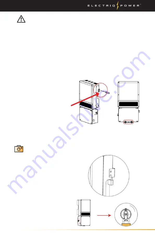
4. Fasten the inverter using the
provided screws in the three
positions circled in red. See
Appendix 5.1 'What's in the Box'
to identify the provided screws,
5mm x 12mm screw, torque min.
2.1 max. 2.5 Nm (min. 1.5 max.
1.8 ft lb).
6. Take a picture within the PowerTools app.
Security Feature
Inverter can be locked for
prevention of theft. Lock will
not be provided by inverter
manufacturer.
DC switch should be in "OFF"
position during installation
and maintenance. A lock can
be applied to prevent any
tampering.
5. Check the inverter nameplate located on the side of the inverter to
determine which system you have.
DC-coupled is the A-ES inverter and the AC-Coupled is the A-BP inverter.


