184
z
Troubleshooting Guide
chap.6
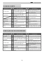
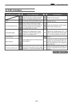
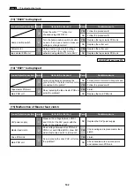
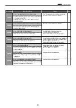
(18) Malfunction of Eject motor
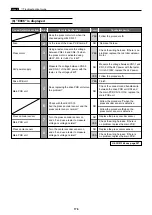
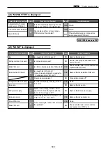
(19) "NO PAPER" is displayed
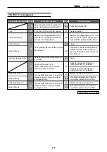
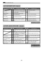
(20) "CLOSE FRONT COVER" is displayed
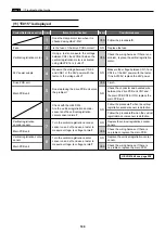
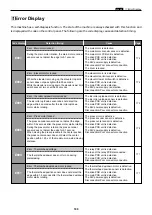
(21) "CLOSE SCANNER" is displayed
Cause/Detective section Procedures
Result
Countermeasure
Items to be checked
24V power supply
1
Measure the voltage between CN2-1
and CN2-5 of the 24V power with the
tester. Is the v24V?
NO
Replace the 24V power supply.
Eject motor
2
Does voltage between drive PCB unit
CN3-16 (+) and -15(GND) show 24V
when eject motor is operated with
HELP-009?
YES Replace the eject motor .
Drive PCB Unit
3
Does replacing the drive PCB unit solve
the problem?
YES Finish.
Main PCB unit
NO
Check bundled wire and connectors
and replace main PCB unit.
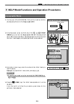
HELP-009
\
see page 220
Cause/Detective section Procedures
Result
Countermeasure
Items to be checked
Paper sensor
1
When paper sensor is checked with
HELP-006, is "1" displayed if paper is
absent and is "0" displayed if present?
YES
Replace the paper sensor.
Main PCB unit
NO
Check bundled wire and connectors
and replace main PCB unit.
HELP-006
\
see page 211
1
Cause/Detective section Procedures
Result
Countermeasure
Items to be checked
Front cover sensor
1
When front cover sensor is checked with
HELP-021, is "0" displayed if front cover
is opened and is "1" displayed if closed? YES
Replace the front cover sensor.
Main PCB unit
NO
Check bundled wire and connectors
and replace main PCB unit.
HELP-021
\
see page 233
Cause/Detective section Procedures
Result
Countermeasure
Items to be checked
Scanner open/close switch
2
When the scanner open/close switch is
checked with volt-ohm-milliammeter,
does it CLOSE if switch is pressed and
OPEN if released?
Is the scanner open/close switch pressed
when scanner unit is closed?
YES
Replace the Scanner open/close switch.
Main PCB unit
NO
NO
Check bundled wire and connectors
and replace main PCB unit.
1
Scanner open/close
switch position
Adjust the scanner open/close switch
position.
Summary of Contents for DP-S Series
Page 1: ......
Page 9: ......
Page 11: ......
Page 16: ...x Dimensions chap 1 15 R8S01001 xDimensions 622 1360 510 228 1080 710 980 688 370 mm...
Page 22: ...v Part Names and Their Functions chap 1 21 44000A1e 2A 2B 2C R8S01006a 2Detailed drawing...
Page 33: ...32 z Scanner Section chap 2 Circuit R8S02E03e...
Page 87: ...86 m Drum Section chap 2 2 Circuit R8S02E30...
Page 171: ...170 MEMO...
Page 193: ...192 MEMO...
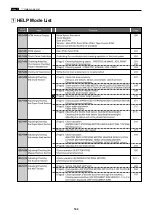
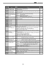
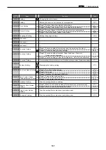
Page 195: ...194 z Help mode List chap 7 z HELP Mode List...
Page 243: ...242 c HELP Mode Function and Operation Procedures chap 7...
Page 270: ...269 c HELP Mode Function and Operation Procedures chap 7...
Page 281: ...280 MEMO...
Page 293: ...292 z Electrical Parts Layout and Their Functions chap 9 MEMO...
Page 295: ...309 294 x Overall Wiring Layout chap 9 Overall Wiring Layout 1 Main PCB 2 2...
Page 297: ...311 296 x Overall Wiring Layout chap 9 Overall Wiring Layout 2 Drive PCB 2 2...

