61
c
Paper Feed Section
chap.2
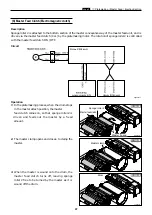
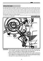
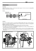
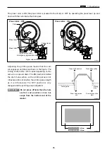
The “paper feed length” is the length by which the paper feed roller feeds out the print paper. When the paper
feed roller feeds out the print paper, the guide roller is pressed against the timing roller and does not rotate;
as a result, the paper arches up between the paper separator and the timing roller, since the distance between
these two items is only 80mm, while the length by which the paper is fed out from the paper feed roller is
95mm. This arching has the effect of correcting any skewing of the paper (as the leading edge is held firm
between the guide and timing rollers). It also has the effect of lessening the load on the timing roller when it
feeds the paper through, thus minimizing slippage.
For feed amount, the leading edge of the paper is detected by the paper top detect sensor and paper feed is
controlled by program(
HELP-039
).
HELP-039
\
see p.244
¡
If paper feed length is too large: the arching dimension will be too large, and if the paper is
of a very stiff type, it will buckle up between the paper feed roller and the paper feed inlet
(upper), causing a PAPER JAM error ("PAPER JAM ON THE FEEDER SIDE").
¡
If paper feed length is too small: the arching dimension will be too small, so that arching
will be unable to correct skewing of the paper, and skewing and wrinkling will be liable to
occur. Furthermore, the slippage that occurs when the timing roller feeds the paper
through will be very large, resulting in printing position errors.
IMPORTANT :
(5) Paper Feed Length
Cam follower
Paper feed cam
Paper feed roller
Guide roller
Paper separator
Timing roller
R8S02045
Paper top detect sensor
Double feed detect sensor
Signal sensor
Summary of Contents for DP-S Series
Page 1: ......
Page 9: ......
Page 11: ......
Page 16: ...x Dimensions chap 1 15 R8S01001 xDimensions 622 1360 510 228 1080 710 980 688 370 mm...
Page 22: ...v Part Names and Their Functions chap 1 21 44000A1e 2A 2B 2C R8S01006a 2Detailed drawing...
Page 33: ...32 z Scanner Section chap 2 Circuit R8S02E03e...
Page 87: ...86 m Drum Section chap 2 2 Circuit R8S02E30...
Page 171: ...170 MEMO...
Page 193: ...192 MEMO...
Page 195: ...194 z Help mode List chap 7 z HELP Mode List...
Page 243: ...242 c HELP Mode Function and Operation Procedures chap 7...
Page 270: ...269 c HELP Mode Function and Operation Procedures chap 7...
Page 281: ...280 MEMO...
Page 293: ...292 z Electrical Parts Layout and Their Functions chap 9 MEMO...
Page 295: ...309 294 x Overall Wiring Layout chap 9 Overall Wiring Layout 1 Main PCB 2 2...
Page 297: ...311 296 x Overall Wiring Layout chap 9 Overall Wiring Layout 2 Drive PCB 2 2...

