128
m
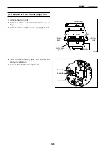
Drum Section
chap.3
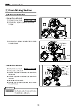
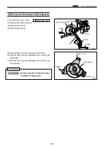
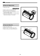
(2) Removal of Master Clamp
(3) Removal of Base Unit
1.
Remove the screen.
2.
Remove 2 screws on the operation side.
3.
Remove the bearing plate and spring.
4.
Remove 2 screws on the anti-operation side to
take out the bearing plate.
5.
Remove the master clamp. The master clamp is
attached to the base with the magnet.
\
See page 127
1.
Remove the master clamp.
2.
Remove lumirror from the sponge surface.
3.
Remove 2 screws, and remove the base unit.
Screw
R8S03088
R8S03089
Lumirror
Lumirror
Screws
Screws
Screw
Screw
Bearing plate
Spring
Master clamp
Base unit
Summary of Contents for DP-S Series
Page 1: ......
Page 9: ......
Page 11: ......
Page 16: ...x Dimensions chap 1 15 R8S01001 xDimensions 622 1360 510 228 1080 710 980 688 370 mm...
Page 22: ...v Part Names and Their Functions chap 1 21 44000A1e 2A 2B 2C R8S01006a 2Detailed drawing...
Page 33: ...32 z Scanner Section chap 2 Circuit R8S02E03e...
Page 87: ...86 m Drum Section chap 2 2 Circuit R8S02E30...
Page 171: ...170 MEMO...
Page 193: ...192 MEMO...
Page 195: ...194 z Help mode List chap 7 z HELP Mode List...
Page 243: ...242 c HELP Mode Function and Operation Procedures chap 7...
Page 270: ...269 c HELP Mode Function and Operation Procedures chap 7...
Page 281: ...280 MEMO...
Page 293: ...292 z Electrical Parts Layout and Their Functions chap 9 MEMO...
Page 295: ...309 294 x Overall Wiring Layout chap 9 Overall Wiring Layout 1 Main PCB 2 2...
Page 297: ...311 296 x Overall Wiring Layout chap 9 Overall Wiring Layout 2 Drive PCB 2 2...


