190
x
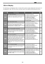
Error Display
chap.6
178
179
180
181
-
182
182
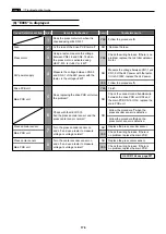
E012
E013
E015
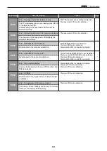
E016
E018
E020
E021
Error : Clamp motor
Within 3 seconds after the clamp motor starts rotating,
the clamp sensor 1/the clamp sensor 2 does not detect
that B mode/C mode is entered.
Error : Scanner stepping motor locked
When moving the slider from end to end, the slider position
sensor 1/the slider position sensor 2 does not detect that
the slider reaches the desired position within 6 seconds
after the scanner stepping motor starts rotating.
When moving the slider from the position other than the
end to the end, the slider position sensor 1/the slider
position sensor 2 does not detect that the slider reaches
the desired position within 12 seconds after the scanner
stepping motor starts rotating.
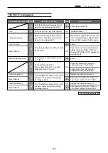
Error : Vertical registration motor locked
The vertical registration encoder sensor does not detect the
edge within 0.5 seconds after the vertical registration motor
starts rotating.
Although the vertical registration motor is rotating, the vertical
registration encoder sensor does not detect the edge for 0.3
second.
Although the vertical registration section is moved by 1.25 x
of the maximum one-side vertical registration moving distance
back to the center, the vertical registration center sensor does
not detect that the vertical registration reaches the center.
Error : Horizontal registration motor locked
The horizontal registration encoder sensor does not detect
the edge within 0.5 seconds after the vertical registration
motor starts rotating.
Although the horizontal registration motor is rotating, the
horizontal registration encoder sensor does not detect the
edge for 0.3 second.
Although the horizontal registration section is moved by 1.25 x
of the maximum one-side horizontal registration moving distance
back to the center, the horizontal registration center sensor does
not detect that the horizontal registration reaches the center.
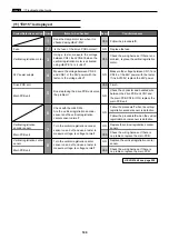
Error : FPGA
Write /readout to FPGA of the main PCB is defective.
Error : Tape cluster cutter motor locked
Tape cutting is defective.
Error : Communication with the tape cluster is not performed normally
Communication between the main PCB and the tape
cluster PCB is defective.
The clamp motor is defective.
The clamp sensor 1 is defective.
The clamp sensor 2 is defective.
The drive PCB unit is defective.
The main PCB unit is defective.
The 24V power supply is defective.
Disconnection/Poor connector connection
The scanner stepping motor is defective.
The slider position sensor 1 is defective.
The slider position sensor 2 is defective.
Poor connector connection
The drive PCB unit is defective.
The main PCB unit is defective.
The 24V power supply is defective.
Disconnection/Poor connector connection
The vertical registration motor is defective.
The vertical registration encoder sensor is
defective.
The vertical registration center sensor is
defective.
The drive PCB unit is defective.
The main PCB unit is defective.
The 24V power supply is defective.
Disconnection/Poor connector connection
The horizontal registration motor is defective.
The horizontal registration encoder sensor is
defective.
The horizontal registration center sensor is
defective.
The drive PCB unit is defective.
The main PCB unit is defective.
The 24V power supply is defective.
Disconnection/Poor connector connection
The main PCB unit is defective.
The tape cluster cutter motor is defective.
The tape cluster cutter home position sensor is
defective.
The tape cluster PCB unit is defective.
The drive PCB unit is defective.
Disconnection/Poor connector connection
The tape cluster PCB unit is defective.
The main PCB unit is defective.
Disconnection/Poor connector connection
Code display
Detection timing
Cause
Page
Summary of Contents for DP-S Series
Page 1: ......
Page 9: ......
Page 11: ......
Page 16: ...x Dimensions chap 1 15 R8S01001 xDimensions 622 1360 510 228 1080 710 980 688 370 mm...
Page 22: ...v Part Names and Their Functions chap 1 21 44000A1e 2A 2B 2C R8S01006a 2Detailed drawing...
Page 33: ...32 z Scanner Section chap 2 Circuit R8S02E03e...
Page 87: ...86 m Drum Section chap 2 2 Circuit R8S02E30...
Page 171: ...170 MEMO...
Page 193: ...192 MEMO...
Page 195: ...194 z Help mode List chap 7 z HELP Mode List...
Page 243: ...242 c HELP Mode Function and Operation Procedures chap 7...
Page 270: ...269 c HELP Mode Function and Operation Procedures chap 7...
Page 281: ...280 MEMO...
Page 293: ...292 z Electrical Parts Layout and Their Functions chap 9 MEMO...
Page 295: ...309 294 x Overall Wiring Layout chap 9 Overall Wiring Layout 1 Main PCB 2 2...
Page 297: ...311 296 x Overall Wiring Layout chap 9 Overall Wiring Layout 2 Drive PCB 2 2...

