36
x
Platemaking / Master Feed / Ejection Section
chap.2
x
Platemaking / Master Feed / Ejection Section
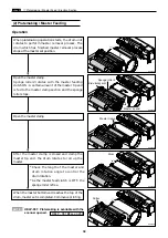
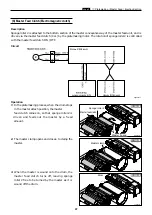
Make the master clamp of the drum unit clamp the master top end, performing platemaking on the master
with the thermal head. (In this machine, the master on the drum is ejected at the same time when
platemaking is performed.)
The master is conveyed to the drum unit via the platen roller and sponge roller1,2 by driving of the master
feed stepping motor, while it is being processed in the thermal head section. Sponge roller2 is driven through
the master feed clutch (electromagnetic clutch), and controls the amount of master conveyed to the master
clamp section of the drum unit with the master feed clutch ON / OFF.
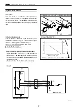
The end mark sensor starts to detect when the end mark (black) section printed on the end of the roll master
is conveyed.
"NO MASTER"
is displayed on the LCD panel. The end mark sensor also detects whether the
master is conveyed properly through the sensor.
Cutter unit
Master feed clutch
Sponge roller 2
Master detect sensor
Master feed cover switch
Platen roller
Thermal head
Master feed stepping motor
End mark sensor
1. Description
Platemaking / Master Feed Section
R8S02013e
R8S02014
Thermal head up/down motor
Thermal head position sensor
Sponge roller 1
Master top sensor
Summary of Contents for DP-S Series
Page 1: ......
Page 9: ......
Page 11: ......
Page 16: ...x Dimensions chap 1 15 R8S01001 xDimensions 622 1360 510 228 1080 710 980 688 370 mm...
Page 22: ...v Part Names and Their Functions chap 1 21 44000A1e 2A 2B 2C R8S01006a 2Detailed drawing...
Page 33: ...32 z Scanner Section chap 2 Circuit R8S02E03e...
Page 87: ...86 m Drum Section chap 2 2 Circuit R8S02E30...
Page 171: ...170 MEMO...
Page 193: ...192 MEMO...
Page 195: ...194 z Help mode List chap 7 z HELP Mode List...
Page 243: ...242 c HELP Mode Function and Operation Procedures chap 7...
Page 270: ...269 c HELP Mode Function and Operation Procedures chap 7...
Page 281: ...280 MEMO...
Page 293: ...292 z Electrical Parts Layout and Their Functions chap 9 MEMO...
Page 295: ...309 294 x Overall Wiring Layout chap 9 Overall Wiring Layout 1 Main PCB 2 2...
Page 297: ...311 296 x Overall Wiring Layout chap 9 Overall Wiring Layout 2 Drive PCB 2 2...


