141
x
Platemaking / Master Feed / Ejection Section
chap.4
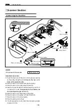
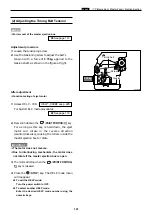
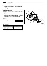
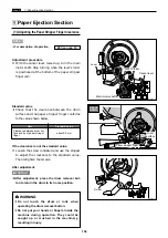
(2) Adjusting the Timing Belt Tension
¡
For removal of the master ejection box.
Adjustment procedure
1.
Loosen the tensioning screw.
2.
Use the tensioning screw to adjust the belt's
tension with a force of
0.75kg
applied to the
tension shaft, as shown in the figure at right.
\
See page 113
NOTE :
After adjustment
¡
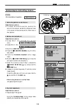
Function testing of eject motor
1.
Access HELP - 009.
For basic HELP mode procedures
2.
Press and hold down the
(PRINT POSITION)
key
.
For as long as this key is held down, the eject
motor will rotate in the reverse direction
(counterclockwise), causing the rollers inside the
master ejection box to rotate.
¡
The motor does not reverse.
¡
Due to interlocking mechanism, the motor does
not rotate if the master ejection box is open.
3.
The motor will stop when the
(PRINT POSITION)
key is released.
4.
Press the
(STOP)
key. The HELP mode menu
will reappear.
\
To exit the HELP mode:
Turn the power switch to OFF.
\
To select another HELP mode:
Enter the desired HELP mode number using the
numeric keys.
IMPORTANT :
\
See page 119
HELP - 009
\
see p.220
Tension
Screw
Timing belt
R8S04008
0.75kg
Summary of Contents for DP-S Series
Page 1: ......
Page 9: ......
Page 11: ......
Page 16: ...x Dimensions chap 1 15 R8S01001 xDimensions 622 1360 510 228 1080 710 980 688 370 mm...
Page 22: ...v Part Names and Their Functions chap 1 21 44000A1e 2A 2B 2C R8S01006a 2Detailed drawing...
Page 33: ...32 z Scanner Section chap 2 Circuit R8S02E03e...
Page 87: ...86 m Drum Section chap 2 2 Circuit R8S02E30...
Page 171: ...170 MEMO...
Page 193: ...192 MEMO...
Page 195: ...194 z Help mode List chap 7 z HELP Mode List...
Page 243: ...242 c HELP Mode Function and Operation Procedures chap 7...
Page 270: ...269 c HELP Mode Function and Operation Procedures chap 7...
Page 281: ...280 MEMO...
Page 293: ...292 z Electrical Parts Layout and Their Functions chap 9 MEMO...
Page 295: ...309 294 x Overall Wiring Layout chap 9 Overall Wiring Layout 1 Main PCB 2 2...
Page 297: ...311 296 x Overall Wiring Layout chap 9 Overall Wiring Layout 2 Drive PCB 2 2...

