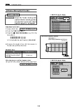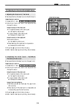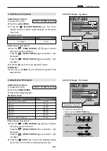
150
v
Drum Drive Section
chap.4
Stopper
Groove
(1) Adjusting the Drum Stop Position
v
Drum Driving Section
Before adjustment
¡
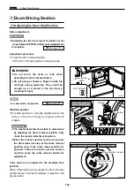
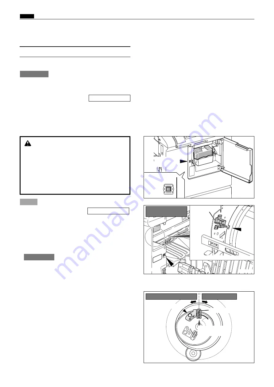
Adjusting the the drum removal position must
be performed AFTER printing speed adjustment
is complete.
Adjustment procedure
1.
Press the drum removal button.
At the drum removal position, a bleep sounds.
IMPORTANT :
\
See page 164
¡
For description of operation .
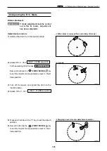
Standard position
¡
The stop position is correctly adjusted when the
groove in the drum flange is aligned with the
stopper.
\
See page 69
NOTE :
R8S04027
R8S04028
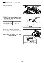
Screw
Drum Removal
detect edge
If the drum is not adjusted to the standard stop
position:
When removing the drum, adjust the drum removal
position sensor so that the stopper is placed in the
groove center
¡
The master detachment position is determined
by adjusting the drum removal position. Only
check the master detachment position.
¡
When the master ejection section is opened,
the drum does not stop at the drum removal
position even if the drum removal button is
pressed. Close the master ejection section
and then press the drum removal button for
adjustment.
IMPORTANT :
WARNING
¡
Do not touch the drum or rolls when
operating the drum removal button.
¡
Do not put your hands or fingers inside the
machine during operation. They could be
caught up or crushed in the machinery,
resulting in injury.
R8S04057
Drum removal
button
Close the ejection
box for adjustment.
LED : light up
Removal pos.:speed decreases
Drum position 1 sensor
speed increases
Summary of Contents for DP-S Series
Page 1: ......
Page 9: ......
Page 11: ......
Page 16: ...x Dimensions chap 1 15 R8S01001 xDimensions 622 1360 510 228 1080 710 980 688 370 mm...
Page 22: ...v Part Names and Their Functions chap 1 21 44000A1e 2A 2B 2C R8S01006a 2Detailed drawing...
Page 33: ...32 z Scanner Section chap 2 Circuit R8S02E03e...
Page 87: ...86 m Drum Section chap 2 2 Circuit R8S02E30...
Page 171: ...170 MEMO...
Page 193: ...192 MEMO...
Page 195: ...194 z Help mode List chap 7 z HELP Mode List...
Page 243: ...242 c HELP Mode Function and Operation Procedures chap 7...
Page 270: ...269 c HELP Mode Function and Operation Procedures chap 7...
Page 281: ...280 MEMO...
Page 293: ...292 z Electrical Parts Layout and Their Functions chap 9 MEMO...
Page 295: ...309 294 x Overall Wiring Layout chap 9 Overall Wiring Layout 1 Main PCB 2 2...
Page 297: ...311 296 x Overall Wiring Layout chap 9 Overall Wiring Layout 2 Drive PCB 2 2...

