185
z
Troubleshooting Guide
chap.6
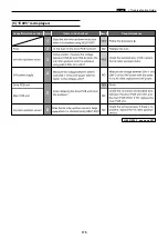
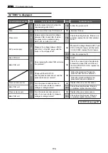
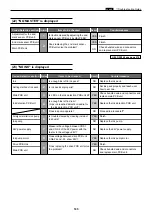
(22) "NO MASTER" is displayed
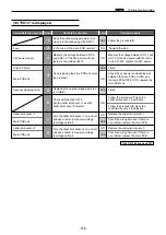
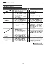
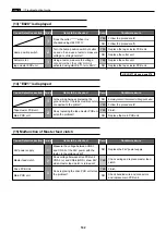
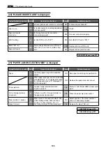
(23) "NO INK" is displayed
Cause/Detective section Procedures
Result
Countermeasure
Items to be checked
End mark sensor PCB unit
2
Does replacing the end mark sensor
PCB unit solve the problem?
Is trouble cleared by adjusting the end
mark sensor PCB unit by HELP-008?
YES
YES Finish.
Main PCB unit
NO
Check bundled wire and connectors
and replace main PCB unit.
1
Adjustment for the end
mark sensor PCB unit.
Finish.
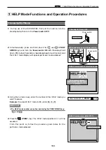
HELP-008
\
see page 218
Cause/Detective section Procedures
Result
Countermeasure
Items to be checked
24V power supply
7
Measure the voltage between CN2-1
and CN2-5 of the 24V power with the
tester. Is the v24V?
NO
NO
NO
NO
NO
Replace the 24V power supply.
Ink pump motor
8
Does voltage between drive PCB unit
CN6-24 and -25 show 24V?
YES Replace the ink pump motor.
Ink pump
Replace the ink pump.
Is trouble cleared by cleaning inside of
ink pump?
Foreign material in ink pump
6
YES Finish.
Does ink pump operate?
5
Proceed to procedure
7
.
Is enough ink left in drum?
(Has ink reached detection needle for
the ink detection PCB unit?)
Ink detection PCB unit
4
YES Replace the Ink detection PCB unit.
Is LED on the ink detection PCB unit lit?
Main PCB unit
3
YES
Check bundled wire and connectors and
replace main PCB unit.
Is ink pack set properly?
Setting method of ink pack.
2
Set ink pack properly and teach user
how to set one.
Is enough ink left in ink pack?
Ink
1
Replace the ink pack.
Drive PCB Unit
9
Does replacing the drive PCB unit solve
the problem?
YES Finish.
Main PCB unit
NO
Check bundled wire and connectors
and replace main PCB unit.
Summary of Contents for DP-S Series
Page 1: ......
Page 9: ......
Page 11: ......
Page 16: ...x Dimensions chap 1 15 R8S01001 xDimensions 622 1360 510 228 1080 710 980 688 370 mm...
Page 22: ...v Part Names and Their Functions chap 1 21 44000A1e 2A 2B 2C R8S01006a 2Detailed drawing...
Page 33: ...32 z Scanner Section chap 2 Circuit R8S02E03e...
Page 87: ...86 m Drum Section chap 2 2 Circuit R8S02E30...
Page 171: ...170 MEMO...
Page 193: ...192 MEMO...
Page 195: ...194 z Help mode List chap 7 z HELP Mode List...
Page 243: ...242 c HELP Mode Function and Operation Procedures chap 7...
Page 270: ...269 c HELP Mode Function and Operation Procedures chap 7...
Page 281: ...280 MEMO...
Page 293: ...292 z Electrical Parts Layout and Their Functions chap 9 MEMO...
Page 295: ...309 294 x Overall Wiring Layout chap 9 Overall Wiring Layout 1 Main PCB 2 2...
Page 297: ...311 296 x Overall Wiring Layout chap 9 Overall Wiring Layout 2 Drive PCB 2 2...

