143
x
Platemaking / Master Feed / Ejection Section
chap.4
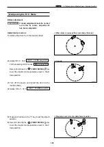
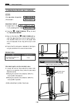
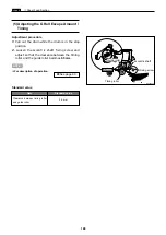
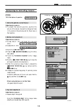
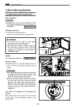
Before adjustment
C mode adjustment must be carried
out After B mode adjustment
has been completed.
IMPORTANT :
Adjustment procedure
1.
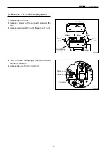
Remove the drum from the machine body.
3.
Turn off the power, and install the drum to the
machine body.
4.
Access HELP - 012.
HELP - 012
\
see p.226
¡
C mode
¡
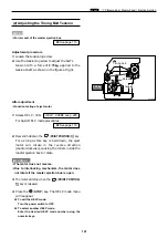
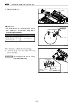
Stopping drum in master detachment position
(3) Adjusting the B / C Mode
¡
When drum is removed from main body ( B mode )
5.
Press and hold down the "1" key to set the detach
position.
6.
Press and hold down the
(PRINT POSITION)
key
to set the master clamp open/close lever to the C
mode position.
2.
Access HELP - 012.
For the accessing HELP modes :
Press and hold down the
(PRINT POSITION)
key
to set the master clamp open/close lever to the B
mode position.
\
See page 199
HELP - 012
\
see p.226
R8S04011
R8S04012
R8S04013
Summary of Contents for DP-S Series
Page 1: ......
Page 9: ......
Page 11: ......
Page 16: ...x Dimensions chap 1 15 R8S01001 xDimensions 622 1360 510 228 1080 710 980 688 370 mm...
Page 22: ...v Part Names and Their Functions chap 1 21 44000A1e 2A 2B 2C R8S01006a 2Detailed drawing...
Page 33: ...32 z Scanner Section chap 2 Circuit R8S02E03e...
Page 87: ...86 m Drum Section chap 2 2 Circuit R8S02E30...
Page 171: ...170 MEMO...
Page 193: ...192 MEMO...
Page 195: ...194 z Help mode List chap 7 z HELP Mode List...
Page 243: ...242 c HELP Mode Function and Operation Procedures chap 7...
Page 270: ...269 c HELP Mode Function and Operation Procedures chap 7...
Page 281: ...280 MEMO...
Page 293: ...292 z Electrical Parts Layout and Their Functions chap 9 MEMO...
Page 295: ...309 294 x Overall Wiring Layout chap 9 Overall Wiring Layout 1 Main PCB 2 2...
Page 297: ...311 296 x Overall Wiring Layout chap 9 Overall Wiring Layout 2 Drive PCB 2 2...

