172
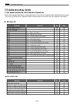
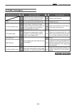
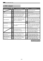
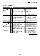
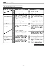
1. Countermeasures for the Defective Operation
CLOSE FRONT COVER
CLOSE SCANNER
E001
E002
E005
E006
E009
E011
E012
E013
E015
E016
E020
E021
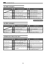
MASTER EJECTION ERROR
NO INK
NO MASTER
NO PAPER
NO USED MASTER CORE
PAPER JAM ON FEEDER SIDE
PAPER JAM ON EJECTION SIDE
PLEASE INSERT CARD
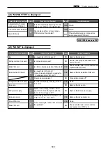
Error : Main motor locked.
Error : Elevator motor locked
Error : Ink roller up/down motor locked
Error : Press motor locked
Error : Thermal head voltage
Error : Thermal head up/down motor locked
Error : Clamp motor locked.
Error : Scanner stepping motor locked
Error : Vertical registration motor locked
Error : Horizontal registration motor locked
Error : Tape cluster cutter motor locked
Error : Communication with the tape cluster is not performed normally
(20)
(21)
(3)
(4)
(5)
(6)
(7)
(8)
(9)
(10)
(11)
(12)
(13)
(14)
(17)
(23)
(22)
(19)
(27)
(25)
(26)
(24)
184
184
174
174
175
176
177
177
178
179
180
181
182
182
183
185
185
184
187
186
187
186
Massage
Remarks
Page
No.
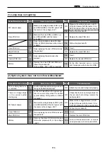
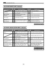
Lamp does not Light Up
Malfunction of Master Feeding Clutch
Malfunction of Master Stepping Motor
Malfunction of Eject (Roll-up) Motor
Optical System Dose Not Move Forward/Backward
Paper Jams in the Paper Feed Side
(1)
(15)
(16)
(18)
(2)
(28)
173
182
183
184
173
188
Massage
Remarks
Page
No.
z
Troubleshooting Guide
¡
When the messages listed below are displayed on the LCD or when trouble such as malfunctioning or a paper
jam occurs, proceed with an inspection following the procedure for the item and take measures accordingly.
Message List
Error item List
z
Troubleshooting Guide
chap.6
Summary of Contents for DP-S Series
Page 1: ......
Page 9: ......
Page 11: ......
Page 16: ...x Dimensions chap 1 15 R8S01001 xDimensions 622 1360 510 228 1080 710 980 688 370 mm...
Page 22: ...v Part Names and Their Functions chap 1 21 44000A1e 2A 2B 2C R8S01006a 2Detailed drawing...
Page 33: ...32 z Scanner Section chap 2 Circuit R8S02E03e...
Page 87: ...86 m Drum Section chap 2 2 Circuit R8S02E30...
Page 171: ...170 MEMO...
Page 193: ...192 MEMO...
Page 195: ...194 z Help mode List chap 7 z HELP Mode List...
Page 243: ...242 c HELP Mode Function and Operation Procedures chap 7...
Page 270: ...269 c HELP Mode Function and Operation Procedures chap 7...
Page 281: ...280 MEMO...
Page 293: ...292 z Electrical Parts Layout and Their Functions chap 9 MEMO...
Page 295: ...309 294 x Overall Wiring Layout chap 9 Overall Wiring Layout 1 Main PCB 2 2...
Page 297: ...311 296 x Overall Wiring Layout chap 9 Overall Wiring Layout 2 Drive PCB 2 2...


